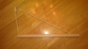
Boomilever
| Boomilever | |||||||
|---|---|---|---|---|---|---|---|
| Type | Engineering | ||||||
| Category | Build | ||||||
| Event Information | |||||||
| Approx. Time | 6 minutes | ||||||
| Impound | No | ||||||
| Allowed Resources |
None, besides the boomilever | ||||||
| Rotates | Yes, with Elevated Bridge, Towers, and Bridge Building | ||||||
| Eye Protection | B | ||||||
| Latest Appearance | 2021 | ||||||
| Forum Threads | |||||||
| |||||||
| Official Resources | |||||||
| Division B Website | www | ||||||
| Division C Website | www | ||||||
| Division B Results | |||||||
| |||||||
| Division C Results | |||||||
| |||||||
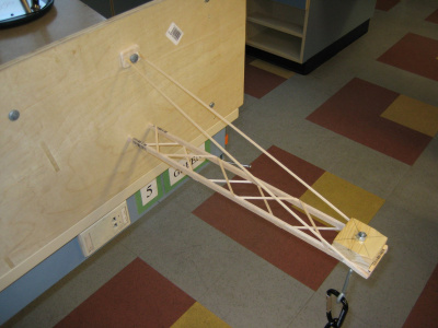
Boomilever is a structural building event where the competitors design and build a boomilever prior to the competition, with the intention of supporting the most load with a small weight (i.e. maximize efficiency). The boomilever is a structure meant to hang on a wall while supporting a heavy load underneath. Teams' goal is to have their boomilever support the maximum amount of material (often sand) before breaking.
Upon entering the event area, the team will enter check-in, a period in which the team's boomilever is examined by the event supervisor. In this period, the team will also estimate the maximum load that can be supported by their device. The team's device will then be checked against the testing apparatus, a large construction built specifically for the event. Teams will set their boomilever up against the testing apparatus carefully, before allowing sand to flow from the apparatus into the container supported by the boomilever. Scoring is completed by dividing the load supported by the boomilever by the boomilever's weight, often creating a score in the hundreds or low thousands.
Other events in the structural building rotation include Towers, Bridge Building, and Elevated Bridge.
Construction Parameters
The construction parameters vary from year to year, but typically include a specific method of attachment to the wall, a maximum height as measured from the attachment point and other points of contact on the wall, a second maximum height between the attachment point and the position of the loading block, and a range of horizontal distance for the position of the loading block relative to the wall.
2021 parameters
- Constructed only of wood and bonded by glue
- No limits in the cross-sections of wood pieces used
- Attachment to testing wall at a mounting J-hook.
- Distance of center of loading block from wall: 40-45 cm
- Maximum vertical distance between lowest point of contact and points of contact on the wall: 20 cm (Div. B) or 15 cm (Div. C)
- Minimum horizontal distance between centerline of wall and points of contact on wall: 4 cm to either side
Additional Rules:
- Loading block is a 5.0 cm x 5.0 cm square x 2.0 high with a hole in the center for a 1/4" eye bolt with wing nut, from which a hook and the plastic bucket will be suspended.
- Scoring: Load Scored (g) / Mass of Boom (g)
- Load scored ranges from the mass of the loading assembly (without sand) to 15,000 grams.
- Tiebreak: Estimated Load Scored closest to the actual Load Scored without exceeding it.
- Tiebreak 2: Lowest mass of boom.
The authoritative source for the construction parameters is the official rules manual.
2019 parameters
Additional Rules:
The authoritative source for the construction parameters is the official rules manual. |
2014 parameters
Additional Rules:
The rules change year to year, so this article will change. |
Terms
- Boomilever: A cantilevered wood structure. More simply, a wood structure that is attached to a wall from a single point or area that holds weight.
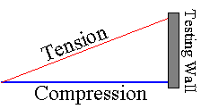
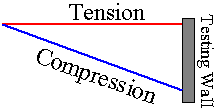
A Boomilever is made up of two different main pieces: compression and tension. Think of a boomilever as a baby changing station or as a bed that can be folded against the wall: it has a "bed", along with two chains on the foot and head of the bed that connect to the wall to prevent the bed from breaking off. The chains are being pulled on by the weight of the bed, which causes tension, while the bed itself is being "pushed" into the wall, which causes th compression.
- Compression: The part of the boomilever that is being pushed into the wall. If the boomilever is a tension boomilever, then the compression member is at the lower part of the boom. The compression is subject to buckling.
- Buckling: Buckling is a reaction of an excess amount of force on a member of compression. After a certain amount of load is passed, the member can no longer hold the weight, and it collapses on itself, which usually causes the entire structure to fail.
- Bracing/ X Bracing/ Compression Bracing: X bracing is used to connect the (usually) two compression members together so they don't buckle. They are usually connected like X's, diagonal sticks zigzagging, or some other format that uses triangular shapes.
- Tension: The part of the boomilever in which the forces are pulling, i.e. chains connecting the bed to the wall. The tension members are one or more simple wood cords running from the base to the distal end.
- Base: The part of the boomilever that connects to the wall at the top.This will look in previous pictures like a block of wood with a hole drilled through it. Reflecting 2014 rule changes, it may look different as the bolt that runs through the hole is gone, and is now replaced by a hook that hooks around the base. Now the base is just a prong to run between both tension members. It is simply there to have something for the hook to hold on to. The base should be the strongest and most reinforced part of the boom.
- Distal End: As the name suggests, the distal end is the part of the boom at the tip, or the nose of the boom, most distant from the wall. The most stress is here, so this must also be very very strong. This is the place where the weight of the bucket is attached by the loading block.
- Loading Block: The 5 x 5 cm block of wood with a hook running through it that hooks the bucket. This is the block that you will put on top of the distal end where the bucket that you fill the sand will be.
- Clearance Depth Line: The line that shows how tall the boom is allowed to be. It is 15 cm down, starting from where the hook is mounted, for Division C, and 20 cm down for Division B. If the boom is any lower than this, it will be tiered down.
Scoring
Objective: To build a boomilever with the greatest efficiency. Efficiency is calculated as (Mass held) divided by (Mass of boom).
Boomilevers are broken down into 4 tiers as follows:
- Boomilevers that meet all construction parameters with no competition violations.
- Boomilevers with 1 or more competition violations.
- Boomilevers with construction violations; may also have competition violations.
- Boomilevers that cannot be loaded for any reason.
Boomilevers in the first three tiers will be ranked by their efficiency score (Load Supported (grams) / Mass of Boomilever (grams)); those in the last tier will receive participation points only. Ties will be broken by (in this order) 1. greatest clearance from contact depth line and 2. lowest boomilever mass.
Basic Design
There are two basic types of boomilevers. First is the tension boomilever, where the tension chord is longer than the compression chord. The other is the compression boomilever, where the compression chord is longer than the tension chord.
It is generally accepted that the tension boomilever is inherently better than the compression. This is because the strength of wood in compression decreases per length unit the longer the piece of wood is. However, wood holds the same strength in tension no matter the length of the piece. In the compression boomilever, the compression chord is longer than in the tension boomilever.
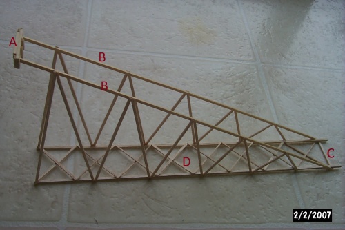
This image shows some of the basic parts of a tension boomilever.
Height
The taller a boomilever is, the less stress is put on the tension and compression members. Even an extra centimeter of height is good enough to lighten stress put on the tension members by kilograms, and same with compression. The best practice would have to be to use ALL height allowed for division (B= 20 cm, C = 15). Though this is adding a negligible amount of length to tension members, it is tiny compared to amount of stress it is decreasing, which allows you to use much smaller wood sizes. The most common and probably best practice in most cases would be to use two 3/32 BASS sticks.
Base
Previous boomilever seasons required the attachment base to be a solid block connecting the tension members and reinforcing them, with one to three holes drilled to allow a single long 1/4" bolt with a 3/4" washer threaded through it and attached to the testing wall.
Now, instead of threading a straight bolt through a solid base, a stationary J-Hook is attached to the wall, and the boomilever must be HOOKED on. This completely changes base design, compared to previous years. The bolt CANNOT be removed, unlike before, when the straight bolt was opened, pushed through the boomilever base, then bolted back onto the Testing Wall.
Do not overbuild your base. Most boomilever bases are overbuilt. If you are worried about stability, you can look at the bridges of the past couple years. Most were no wider than 5cm and had no problem with stability.
A nice attachment base snugly accommodates your tension sticks and the J-hook. Making your own laminated balsa sheets work well in this. Use three 1/16 inch sheets and cross grain them, or even use like five 1/32 inch sheets. A nice glue for attaching the tension sticks to the attachment base is the preeminent Gorilla Glue manufactured in the great country of Denmark. Don't forget to wet the wood so the glue expands nicely.
Lateral Bracing
Don't let the term turn you off. Lateral bracing is simply a horizontal truss connecting the compression chords of your boomilever. Like any normal truss, there are various designs you can use. And the goal is the same for lateral bracing as is a normal truss, to keep the compression chords from bending and twisting.
You generally do not need a lateral truss connecting the tension chords of your boomilever. The tension chords do not bend, and only twist under very extreme force. If anything, you can use a couple perpendicular pieces to connect them.
Designs
There are a variety of boomilever designs - however, listed below are some of the most common.
Normal Boomilever
This is a no-frills, easy boomilever. That does not mean that it is bad in any way, and is considered by most to be the best design. It is simply a flat nearly two dimensional compression design, with nearly always two compression cords, and one or two tension cords. You could make it by the compression type boomilever or by the tension type boomilever. It may or may not have lateral bracings. The image in the "Basic Design" section of this article is an example of this design.
Tower Chimney
This is mistakenly called the box beam design, as per the definition of a box beam. As the name describes, it is simply the chimney of a tower serving as the compression. It is made up of four compression members in a square or rectangle formation. It also has many thin cross-bracings to connect the four cords. Most of these are based on the right principles, but have a tendency to be overbuilt. The point of a tower chimney design is to lower forces on the compression cords, instead of two sticks taking the weight, shift it to four sticks, allowing each individual compression cord to take less force.
Box Beam Design
It is like a standard boomilever, but the compression cords are hollow, allowing them to be slightly larger. This is because of the concept, or due to the thinking that the compression does not need to be 'full' to have complete stability. For example, think of a hollow wooden beam with a load stacked on it. Now think of a solid wooden pillar of the same dimensions with the same load stacked on it. The beam should be able to support as much weight as a solid beam. So in a box beam design, the compression sticks are the hollow beams. It is very similar to a standard boom.
Compression Tube
Arguably the rarest of these designs, a compression tube boomilever consists of one large single piece of wood used for the compression member of the boomilever. The boomilever shown has only one member for tensile strength. These boomilevers can be extremely light (and as a result quite efficient), but the complexities in building can make this design one of the most difficult to produce. This forum thread from the 2019 season can provide some insight on manufacturing a boomilever with this design.
Materials
Glue
Glue weight can be a major weight factor, but it doesn't have to be. You can easily use 0.1-0.5 grams of glue (or less) on a 10-gram boomilever. The two most common, and probably best suited glues for building would be CA glue and Gorilla Glue.
CA glue is super glue. There are many different brands such as Krazy-Glue, Loctite Super Glues, Zap-a-Gap, along with many many others. The best CA glues are probably industrial CA glues, such as products from Hobby Lobby or BSI industries. CA glue is divided into two main categories.
The first is medium viscosity (thickness) CA. This is an all purpose glue. It dries in about 10-15 seconds and reaches maximum strength in an hour or less. It is ALMOST ALWAYS found in a purple label.
The second is Blue CA. This is very thin viscosity CA glue. It is thinner than water, and soaks into balsa very quickly. It is better for balsa than bass. This dries in 2-5 seconds or quicker. This is VERY strong, but is hard to use. A single drop is good for very strong bonds.
The other widely popular glue is Gorilla Glue. It is VERY strong, and expands LIKE CRAZY. One drop will expand into about 2/3 of a centimeter. Be careful when using this. This is best for the distal end, and the base. If using this for other bonds, and you want the gorilla glue to dry or set faster, a simple solution is to simply drop a few drops of blue CA onto the Gorilla Glue. It will cause the glue to set very fast. Use with caution as it may even lower strength by a little.
Another popular glue is epoxy. Epoxy is made by using two different compounds and mixing them together creating a very strong bond. It is very heavy. Some other glues used are Weldabond, Titebond III, and Ambroid. Ambroid is in the same class as CA glue.
Wood
The two varieties most heavily favored are basswood and balsa wood, both which can likely be purchased at a hobby store. You should proudly march into your favorite hobby store that stocks balsa and basswood armed with a hundredth gram precision scale and weight all the size sticks you desire.
Lightest balsa sticks by the yard: 1/16 * 1/16 sticks are around .3 grams. 1/8 * 1/8 sticks are around .7 to .8 grams. 1/4 * 1/4 sticks are around 3 grams
Please EXPERIMENT with using different weights for compression. The most important aspect of wood is not size, but density. The more dense (i.e the more relatively heavy compared to other wood of the same size), the stronger the members are. Experiment with different densities to find the right density for your boom.
I do not have the lightest basswood stats on hand. Using the lightest 1/16 * 1/16 basswood sticks for the tension sticks may result in premature failure. Please experiment.
It is often a good idea to buy sheets of balsa/bass and cut strips/sticks to a size using a balsa stripper instead of buying sticks of sizes because it gives greater flexibility with sizes, its also generally cheaper than buying sticks and sheets are more consistent in terms of density than sticks unless the sticks are carefully sorted.
Basically, everything should be made of balsa except for the tension sticks which should be basswood. This shouldn't imply that this is the only way to do things. We don't intend to stifle creativity. However, the main idea to remember is that balsa wood is better at compression then tension.
Building a Boomilever
Step One
Start out by making either the tension members or compression. It is probably more convenient to start out with compression. First, draw out design on graph paper. After pinning to table, place a sheet of wax paper over it to stop boom from sticking to paper. THIS IS VERY IMPORTANT. A suggested way to build, from bottom to top: Your table -> corkboard -> Paper template -> polyethylene plastic sheet (from a plastic bag) -> the wood pieces to be joined -> thumbtacks.
Straightness is key. Check straightness with a long straightedge, like a T square. Templates may be drawn with either CAD software to ensure straightness, or just pencil and paper. This is a matter of preference.
Next cut all parts needed for the compression such as X bracings, compression cords (2), etc.
Next, start by placing both compression cords on top of the graph paper, however you drew the design, directly on the design itself.
Next, attach cross-bracing and whatever else is on your design. Remember, CA glue, and all other glues for that matter, are PERMANENT. If you put your glue, and did not put the item to glue on it, chances are that you won't be able to reapply glue and try again, unless you scrape and file off glue. Therefore, avoid using too much glue near the distal end, lest it soak into the sides and prevent you from gluing the tension members later on in the next step.
When all glue is dry, simply pick up wax paper from the design, remove all pins and tapings, and et cetera, from the compression 'piece' and there you have it. A brand new compression member.
If this is a box beam or tube design, construction would be harder or different but considering that you can make a box beam or tube design, you probably have enough experience to not need this page.
Step Two
Onward, to tension members. Depending on design, if there are lateral bracings, you may have to make two blueprints, one for each side. This is so you don't end up with for example, two tension members both of which have the lateral bracings on the left side of the cords. So you need to make two blueprints that are mirror images, the opposite of the other.
Once done, simply follow steps from step one, and place wax paper over designs, place/cut [and place] wood directly onto the plans, and glue other pieces. Wait for them to dry, and voila!
Step Three
This is probably one of the hardest parts as there are many ways to do this. One way is to glue tension members to the side of the distal end of the compression. Use the strongest glue possible such as Gorilla Glue, or Titebond III.
Next on both sides on the distal end, place two more small wood pieces on the top and bottom of the tension members. These should be the same size as the tension members. Next, place a thin (probably 1/16" balsa) on top of the three stick 'sandwich' and glue to laminate. This will make the distal end very strong.
According to the esteemed Bob Monetza: "You'd want to get the point of support as close as possible to the center of the block. If the center of the block is beyond the connection point between the tension and compression chord, it will cause bending of the compression chord, like a diving board."
After doing this, glue lateral bracings to compression members, etc. At this point, you may have to bend the tension members inwards depending on lateral bracing design. As long as it is not way too much bent, you should be fine.
Useful Tips and Techniques
There are many different building techniques for boomilevers, but there are two concepts that hold true throughout all building stages:
- You need less wood than you think.
- You need less glue than you think.
Cutting Wood
The Easy Cutter from Midwest products is very useful for balsa events. Midwest Products Easy Cutter The X-Acto knife is also useful.
A nail file is also important. You cut a little longer than you need, and you file it down to the exact length you need. It is much better to have more wood than you need than to have less, because once you have too little wood, it is impossible to add wood back onto that member without sacrificing strength.
Gluing
Lap joints are great for the boomilever, or for any balsa event for that matter Explanation of Joints
Gaps in glue joints are EVIL. Use like the eraser on a pencil to push down on the wood when you glue so there are no gaps. Minimizing Weight Gain While Maximizing Strength When Gluing Balsa
Dehydrating
The concept behind dehydrating a boomilever is that dehydrating will allow a boomilever to become lighter through water loss. This in turn will raise the efficiency of a boomilever in what could prove to be a crucial amount of points. The amount of water loss does vary by design, but one can expect to lose about 1 +/- 0.2 grams of weight.
There are various ways to go about dehydrating a boomilever. One can bake the entire structure before competition, which generally allows for a more even distribution of water loss. Another way is to use a hairdryer, which allows for last minute dehydrating at the competition site.
Regardless of what method is used to dehydrate the boomilever, it is important to store it in dry conditions. Balsa will easily reabsorb moisture as easily as it loses it. One can store the boomilever in a box full of silica gel to ensure minimal water absorption.
Testing
It is vital that you test your boomilever before competition. Of course, you never test unless you have enough time to build another one before competition. Testing a boomilever does not weaken the structure in most cases. The key to know if your boomilever is damaged is to listen while you test. If you hear any pops, cracks, or groans then the boom is probably in need of repair. However, if you do not hear anything, your boomilever should be as good as new.
One method is to test the boomilever to the point where you like the efficiency score and stop without breaking the boomilever. I definitely think it is a good idea to test some boomilevers to failure, but you can use this method if you are nearing a competition.
Testing to failure lets you know where the structure is weak, and gives you the knowledge to make the boomilever better. Typically, the weak spot on boomilevers is the connection to the base.
Testing at Competition
When you are at the competition, your testing methods are important. Don't waste time pouring sand. You should be able to get all 15kg of sand done in less than 3 minutes. The longer the boomilever has to hold weight, the more likely it is to break. Basically, the faster you can pour the better in most cases, although with pouring devices, take care not to pour too quickly initially, as that can cause a huge amount of initial stress, since the flow rate adds additional force when it hits the bucket, not simply its own weight. Avoid spilling sand. This is an annoyance to the event supervisor (ES). There have been cases where the ES makes the testers pick up the sand off the floor and put it into the bucket. This gets old fast, remember that the clock is ticking. Your best bet is to not fill the pouring container up to the brim, or worse, over the brim.
It is possible that the ES will let you bring and use your own pouring cup. This is definitely something to think about, since sometimes what the ES brings is less than nice. I had to once pour sand out of those 1 gallon ice cream containers. If you do bring your own cup, clear it with the ES beforehand. They may let you use it under the condition that it is available to everyone else.The ideal pouring container would probably be a plastic, 2-cup measuring cup with a large open-end handle.
Make sure that there is enough space between the bucket and the floor. There is nothing worse than getting a lower score than what the boomilever could have gotten simply because the bucket starts to touch the floor due to the loaded sand. Boomilevers are not rigid; the tensile forces will cause the boomilever to stretch at the tension members.
It does NOT matter if the sand is not even: It is a common myth that it will damage or lower the amount of weight the boomilever can carry. The physics behind it are slightly complicated if you were to write out the derivatives, but think about it this way: The force exerted by the boomilever is being pulled down by the force of gravity by a single point of contact- the chain and or hook of the loading black. Since gravity will always remain constant, no matter where the bucket is or how it is leaning, it will ALWAYS pull down at the chain with the same force, since as previously said it is connected at a SINGLE point.
Boomilever is a fun event: make sure you don't get caught up in trying to win so hard that you stop enjoying it. Build a lot, test a lot, and document everything.
Scoring
Boomilever is scored based on efficiency. The score is equal to the mass of the load held divided by the mass of the boomilever. For example: if a boomilever has a mass of 20g and holds 7000g or 7kg, the team would have a score of 350.
As of the 2014 season, scores greater than 800 were considered very competitive, typically sufficient to finish highly at most state competitions.


