SkyCiv
SkyCiv is a structural analysis software that may be used for the Boomilever event and is the platform on which Digital Structures is run. This page serves as an introduction and tutorial to SkyCiv.
Getting Started with SkyCiv
SkyCiv is an in-browser cloud-based software (i.e. it is not downloaded but is accessed by a URL). SkyCiv offers many applications, of which Science Olympiad uses the Structural 3D (S3D) application. In S3D, SkyCiv performs structural analysis by simulating three-dimensional structures as members and nodes with their properties defined by materials, sections, and supports. For Digital Structures, S3D is used in conjunction with the Science Olympiad add-on.
Licenses
SkyCiv is available via a 14-day free trial with a newly registered account or a paid license at $10 per month for a 6-month student license. However, with the free trial, you may be limited to a small number of members that is not enough to build a complete Boomilever.
As a sponsor of Science Olympiad, SkyCiv is currently offering an 8-month license for $50 (approximately $6.25 per month).
Terminology
The following terms describe tools used to simulate a Boomilever structure in software. Understanding their functions will be helpful for following the guide on this page to making your first Boomilever in SkyCiv.
| Term | Definition |
|---|---|
| Nodes | Nodes are points in three-dimensional space that can be used for defining members, supports, or loads. Every project starts with nodes because they tell the software where things go! |
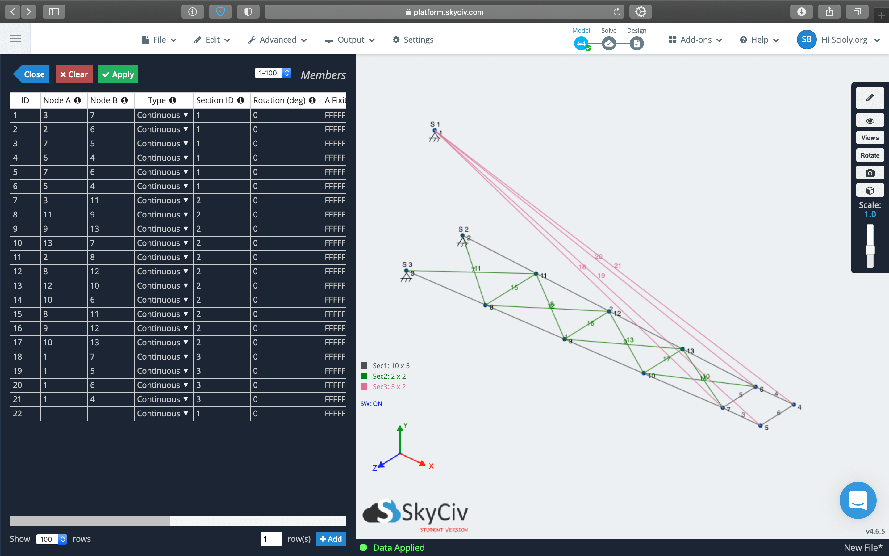
| Members | Members are beams that connect two nodes defining their lengths. Each member also has a section specified. Together, these tell the software how long, how large, and how strong each member is. |
| Sections | Sections are defined as cross-sectional geometries (i.e. how large) with properties from a material (i.e. how strong). For example, a section could be 2 mm by 3 mm rectangular with material properties of balsa wood. |
| Materials | A material is defined by physical properties such as its Young's modulus, Poisson's ratio, ultimate tensile strength, etc. You do not need to understand what these terms mean; the Science Olympiad add-on automatically loads a list of materials. |
| Supports | Supports can be added to nodes to limit their degrees of freedom (translational and/or rotational). For example, a Pin Support allows rotation of a member about a node but not translation. |
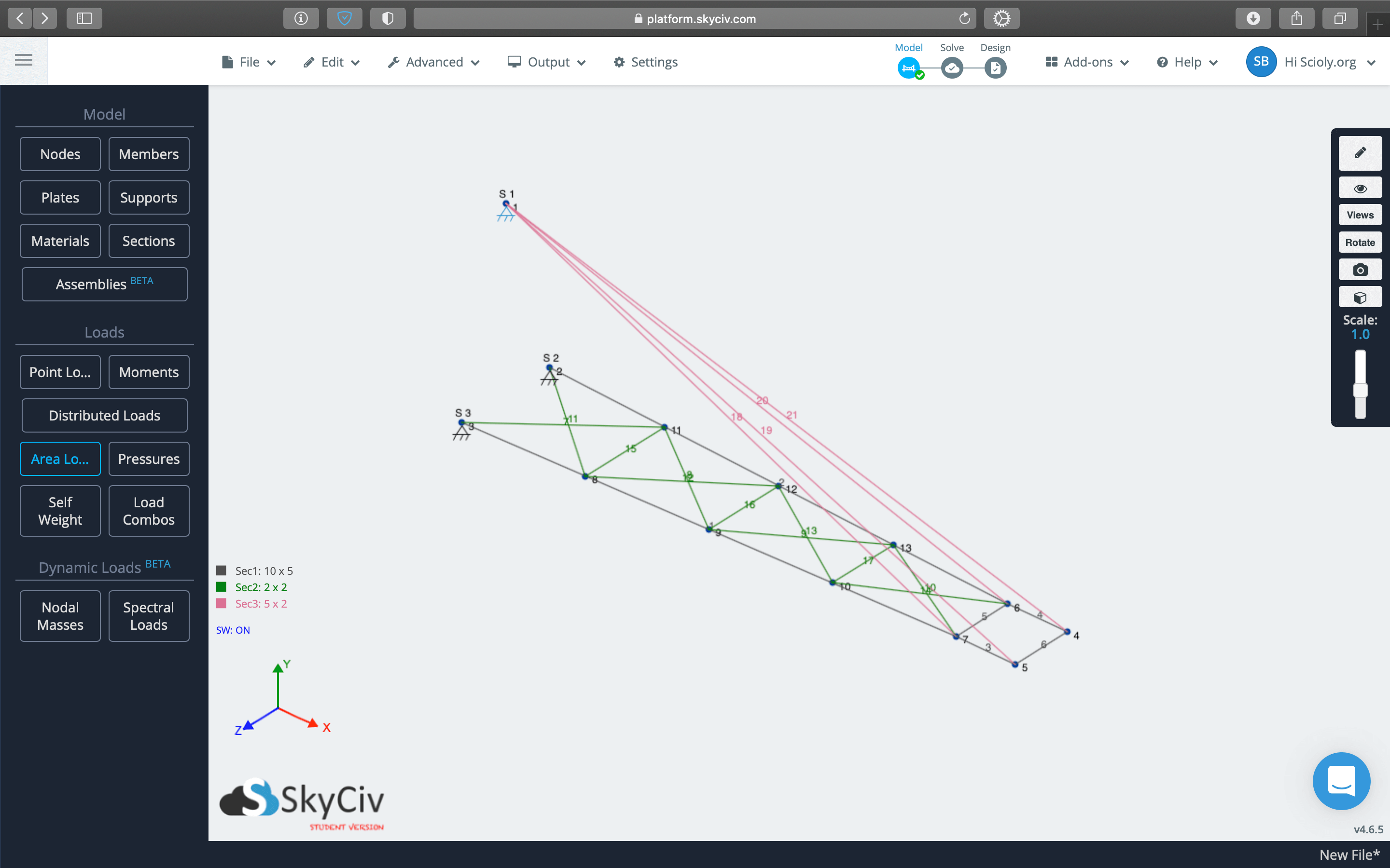
| Loads | Loads are forces applied to members at a point or over an area. Digital Structures uses the Area Load which simulates the force applied over an area by a Loading Block in Boomilever. |
Controls
Like common three-dimensional modeling softwares such as those for computer-aided design (CAD), SkyCiv allows orbiting and panning around a model. These controls along with others are explained in the table below.
| Effect | Control |
|---|---|
| Orbit: rotates around an object in space. | Click + Drag |
| Pan: changes the position without rotation of the model relative to your view. | Shift + Click + Drag |
| Zoom in or zoom out: enlarges or reduces the size of objects in your view. | Scroll |
| Window selection: selects objects (nodes, members, etc.) within the window created by your cursor. | Control + Click + Drag (Windows) Command + Click + Drag (macOS) |
Enabling the Science Olympiad Add-on
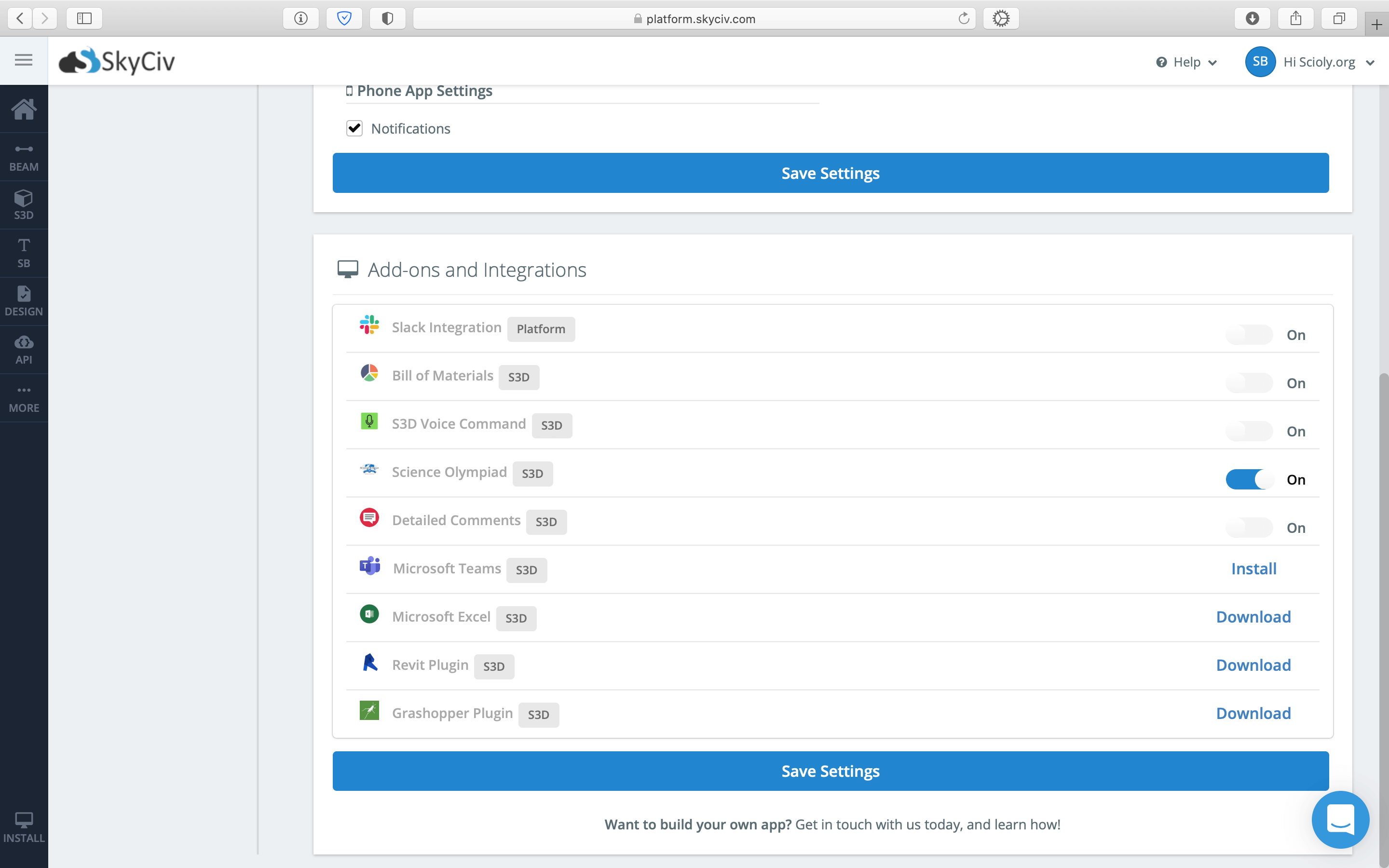
The Science Olympiad add-on is a feature developed by SkyCiv with Science Olympiad, Inc. specifically for Digital Structures. This add-on allows a 'Competition Mode which limits materials to a few densities of balsa wood, limits the number of times students can test their device, checks for construction violations, and submits design files to tournament officials during the competition. Once Competition Mode is turned on, it cannot be turned off for 48 hours.
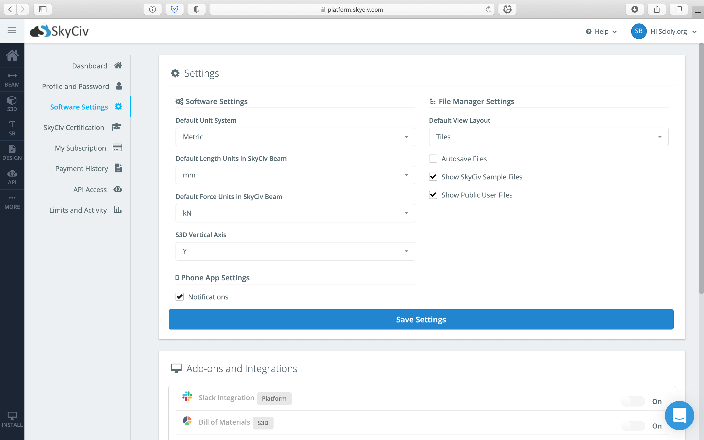
The add-on can be enabled in SkyCiv by clicking Hi YourName > Account Settings > Software Settings > Science Olympiad [S3D] > On.
Starting a Project
To start building a Boomilever model in SkyCiv, you'll need to open the Structural 3D (S3D) application. This can be accessed via the S3D link on the platforms page. Once within the S3D application, you can choose to use the Science Olympiad add-on, which is required in competition for Digital Structures. (Enabling this add-on is explained in the previous section.)
| Creating a New Project | |||
|---|---|---|---|
| Step 1 | Step 2 | Step 3 | Step 4 |
|
|
|
|
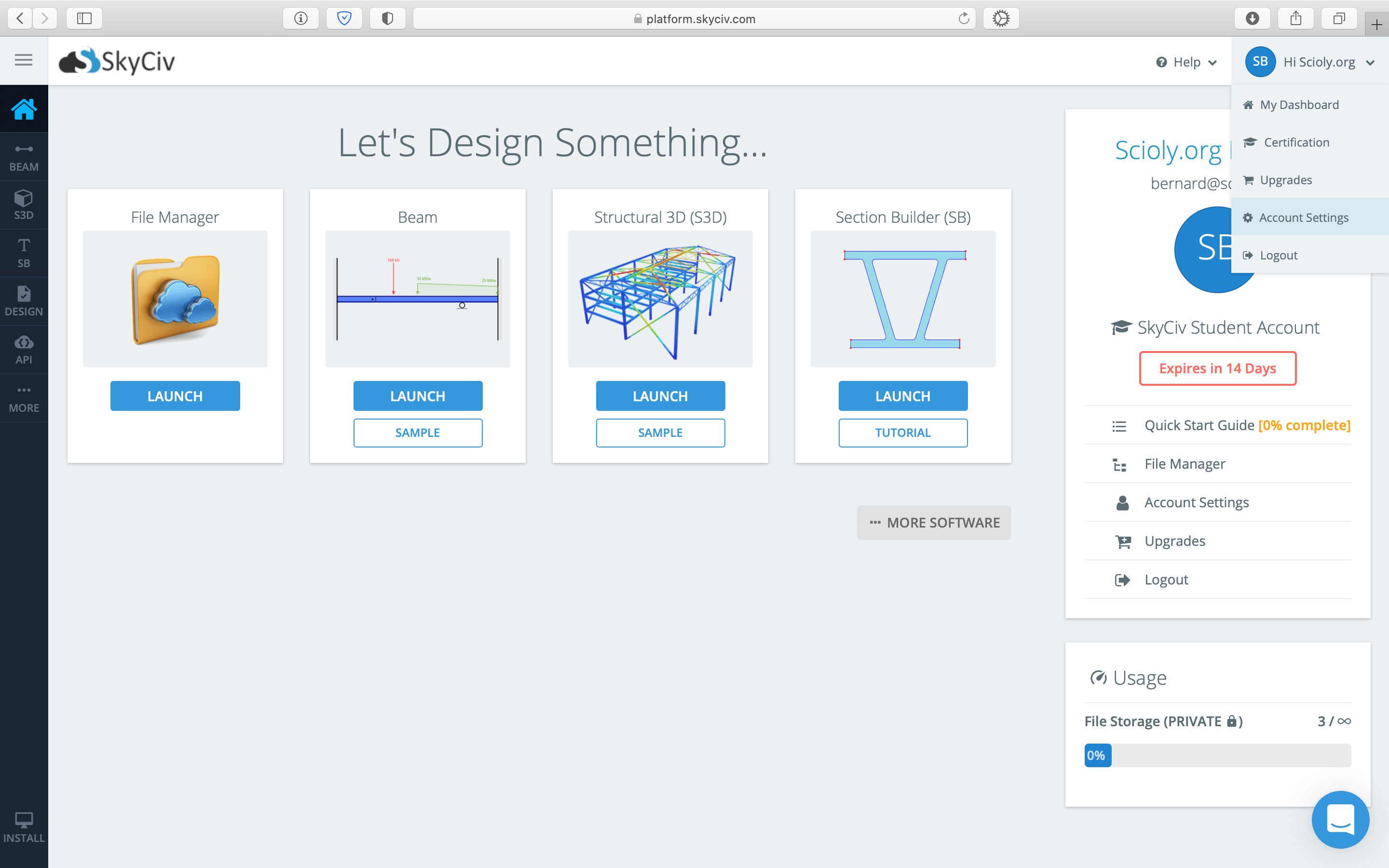
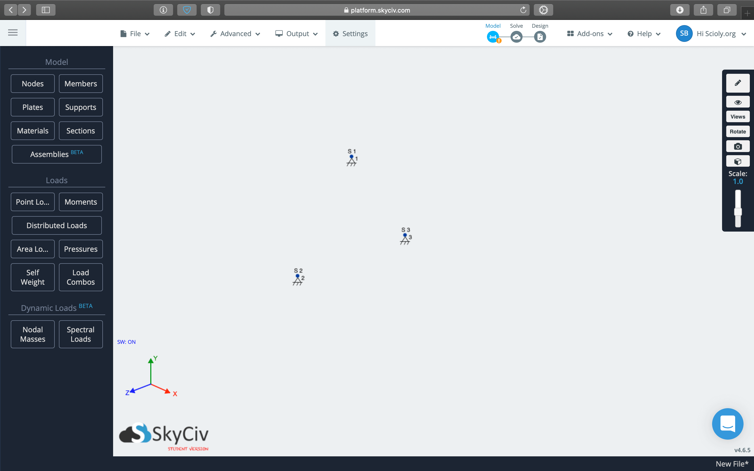
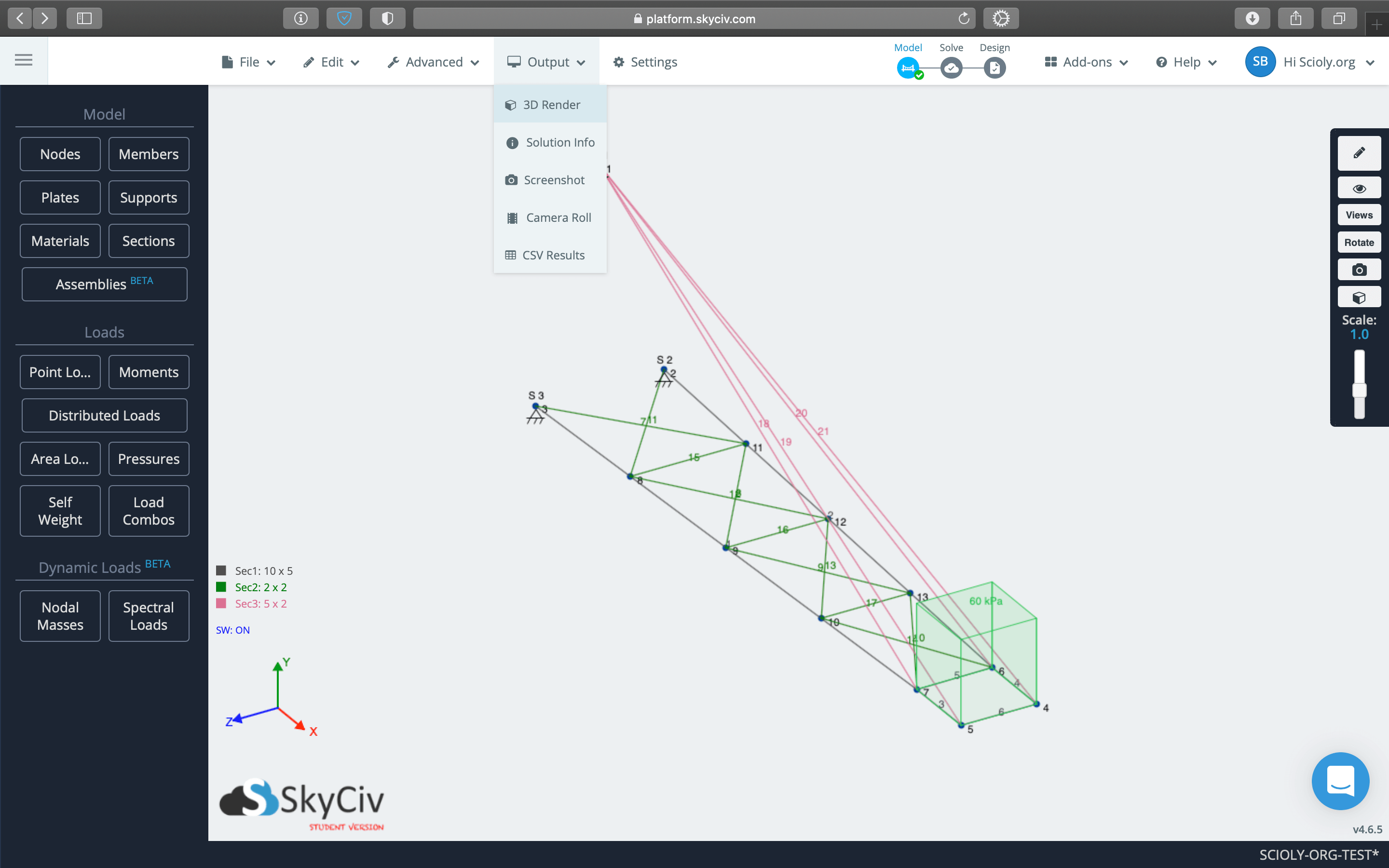
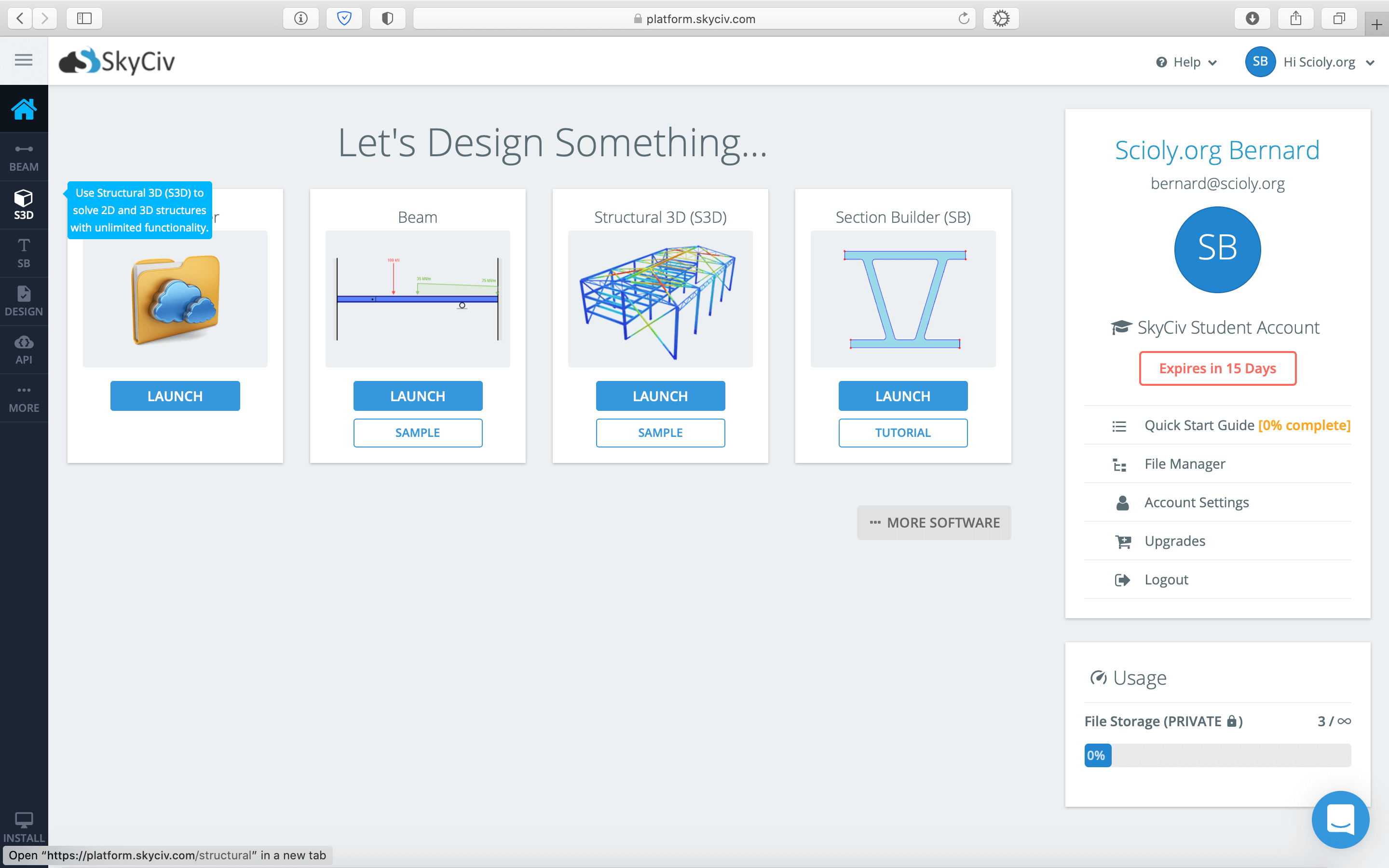
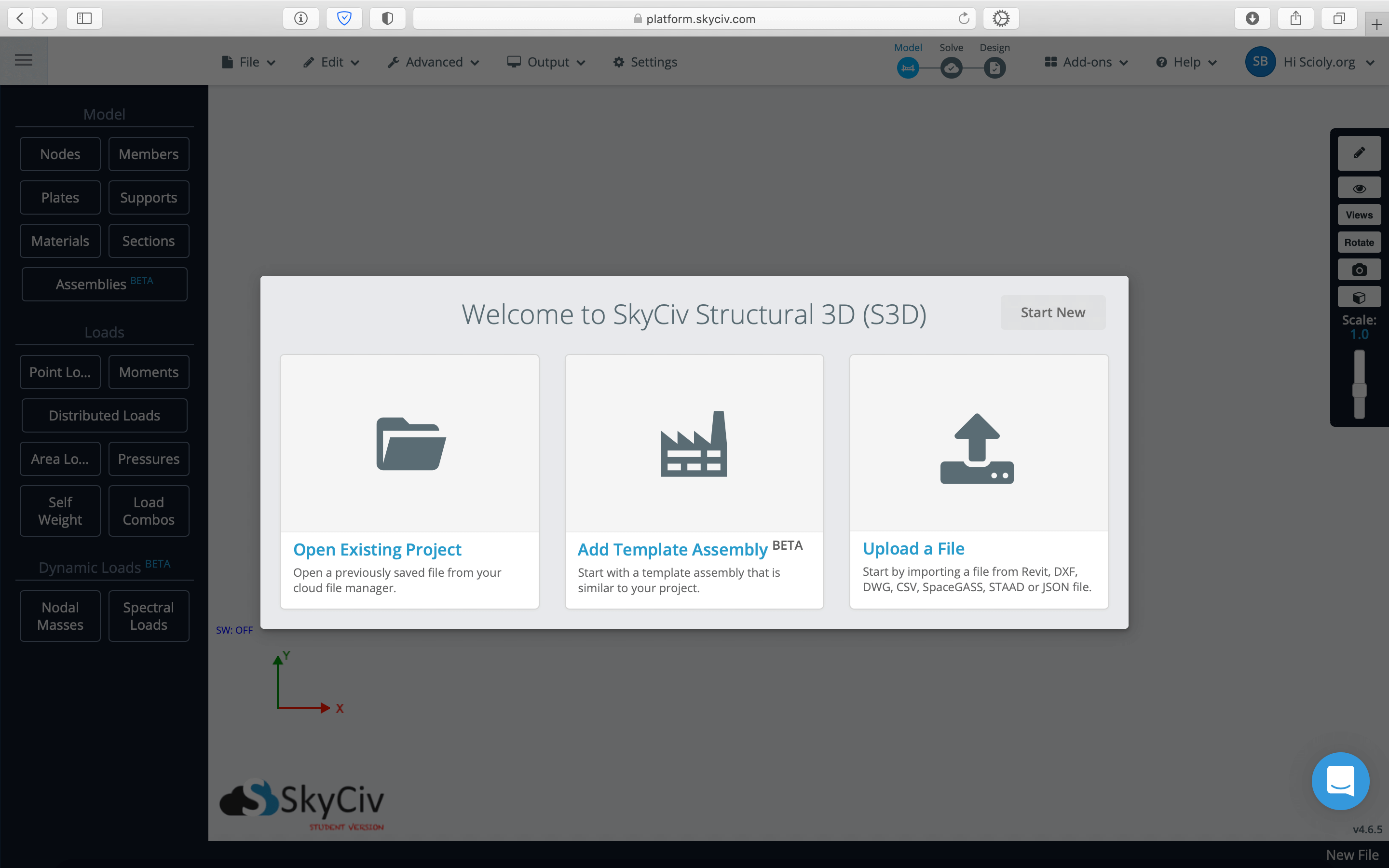
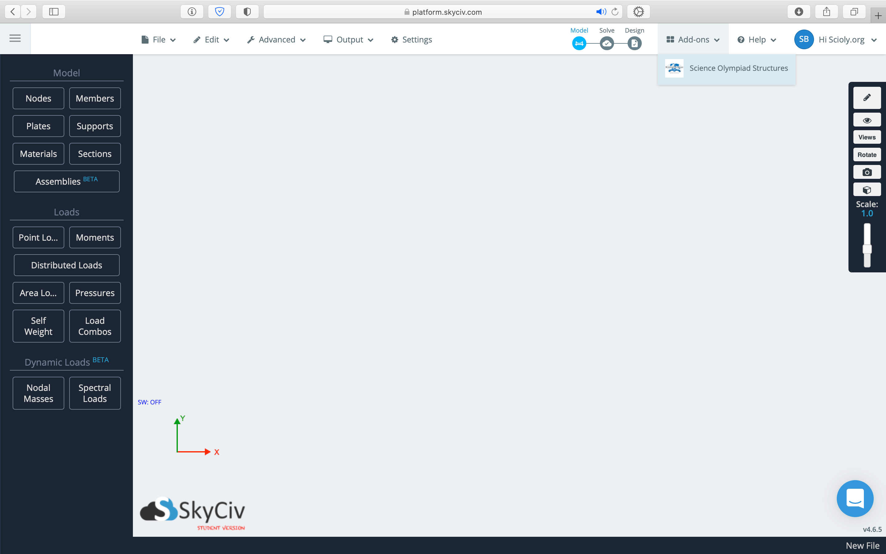
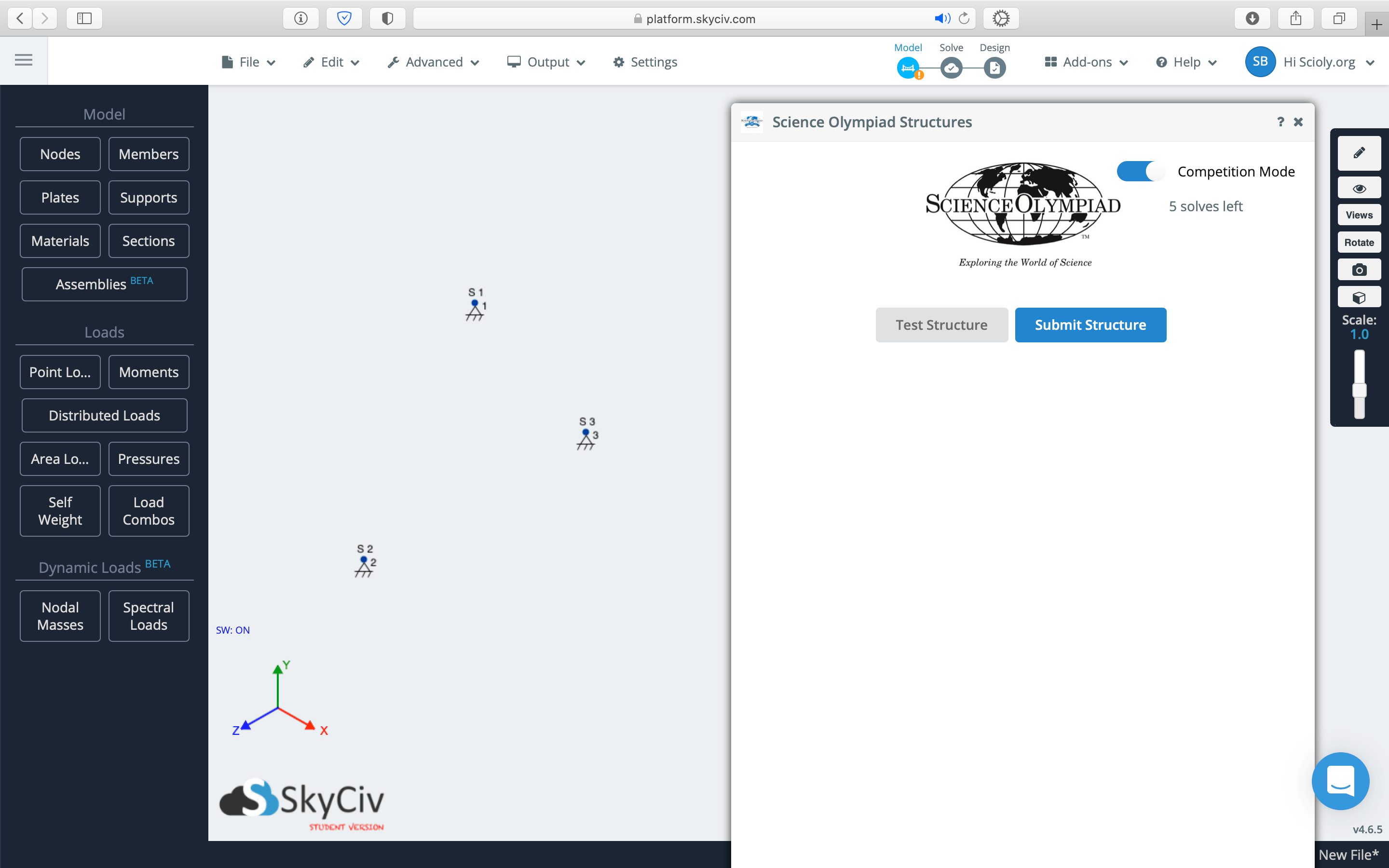
| From the dashboard at platform.skyciv.com, click on the icon for S3D in the left toolbar. | After entering the S3D application, click Start New to start a new project. | To use the Science Olympiad add-on, click on the Add-ons menu in the upper right and select Science Olympiad Structures. | Using the Science Olympiad add-on automatically sets materials, defines three supports, and opens a panel that can be used for testing the structure with Science Olympiad specifications. |
Setting Preferred Units
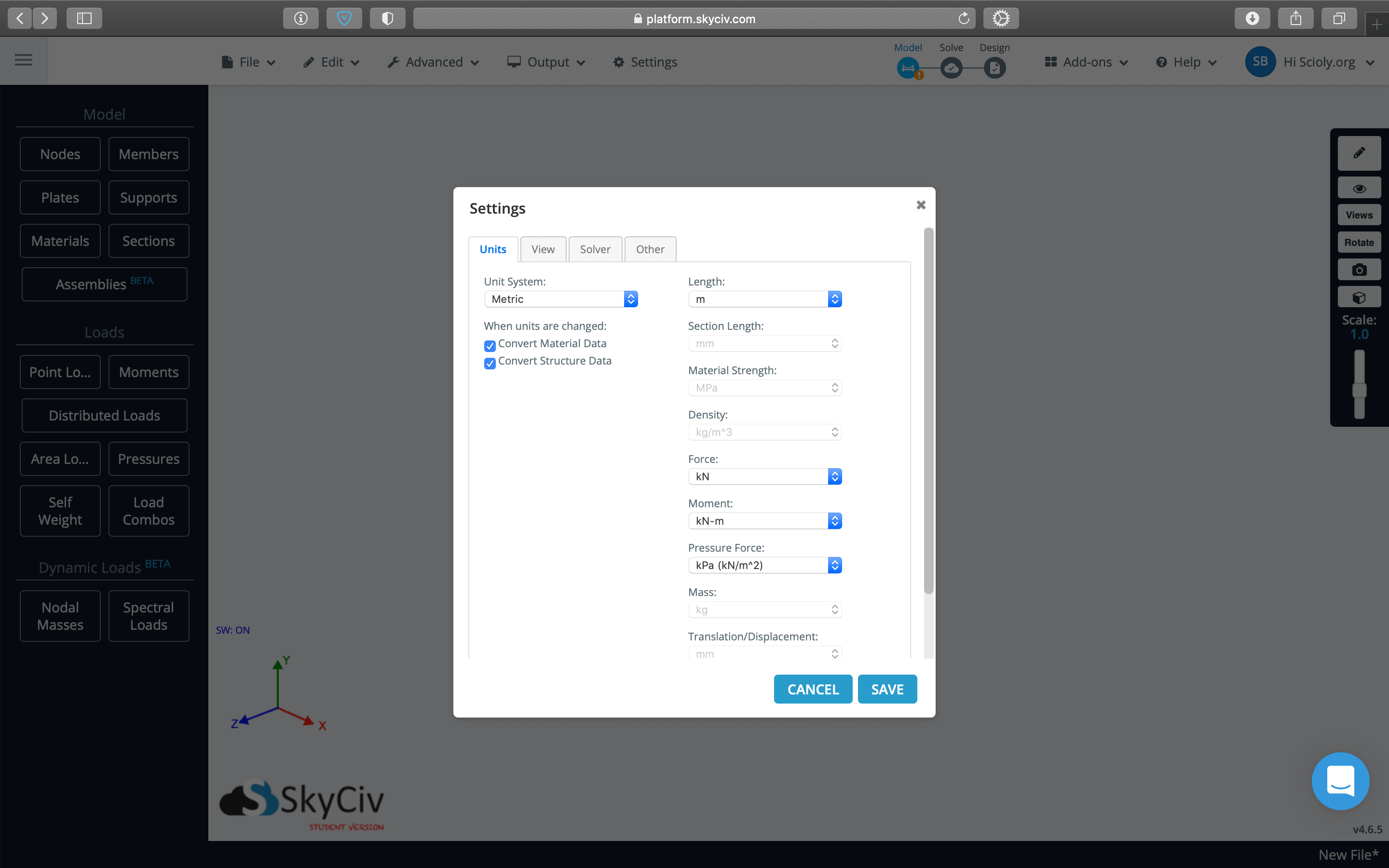
You can set preferred units for your entire account or for a single project. Set units for your account via Account Settings and for a single project via Settings within S3D.
Deciding Your Workflow
For every Boomilever model in SkyCiv, you'll need to define nodes, members, sections, supports, and loads, but the order in which you do so is up to you. While you must define nodes before members and supports and loads, the latter three can be defined in any order.
While SkyCiv recommends defining nodes, members, supports, sections, then loads, you could choose to define sections first as that allows you to know exactly where your nodes need to be to avoid touching below the Contact Depth Line. Or you could define nodes first, knowing that you might need to adjust their positions later as you experiment with section sizes.
It may help to sketch your Boomilever on paper before adding anything in SkyCiv. Then, with your plan, you can add all of your nodes together, then members, etc.
You can decide or change your workflow as you go. Whatever you do, having a plan ahead of time will allow you to be as efficient as possible on competition day.
Defining Nodes
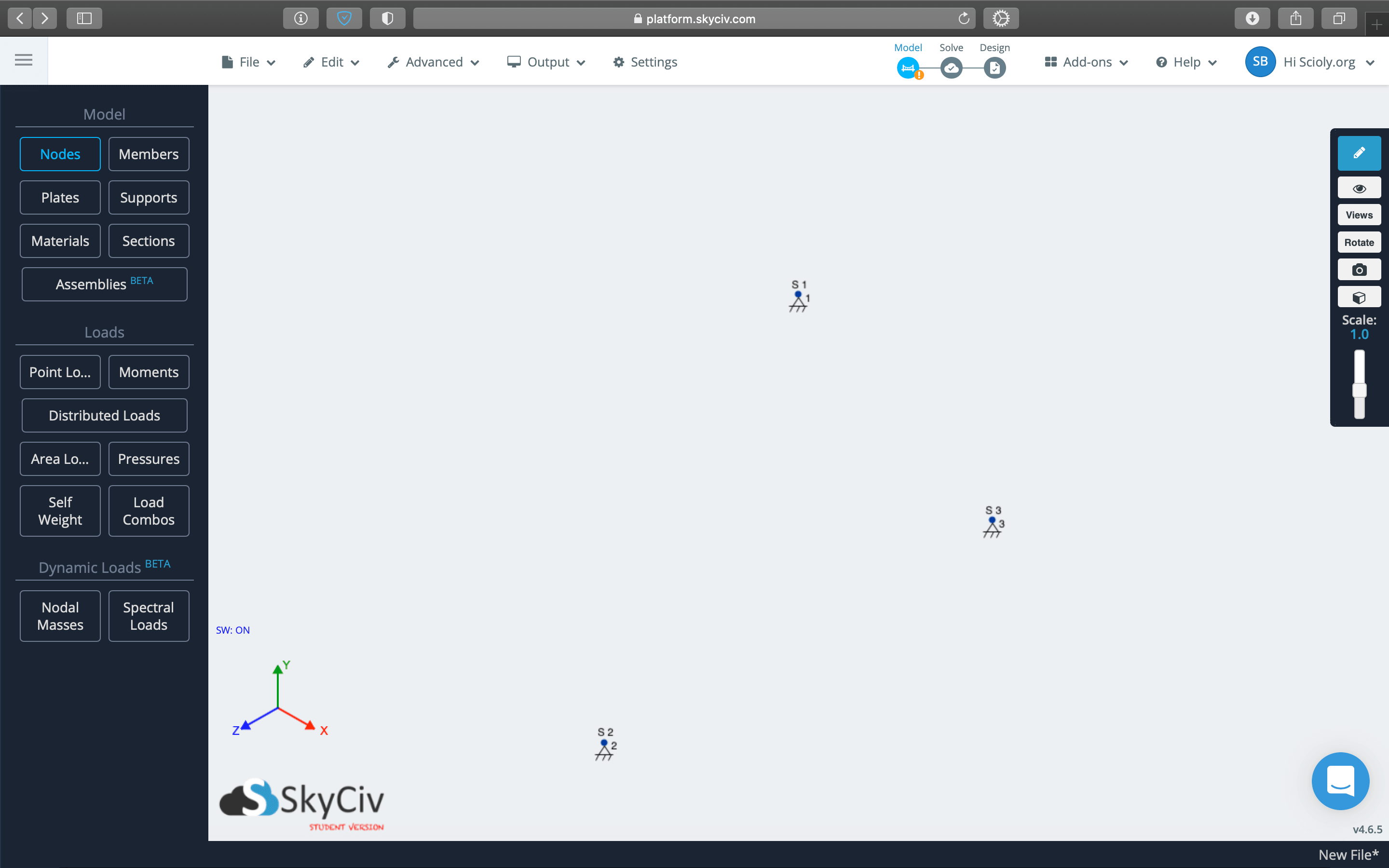
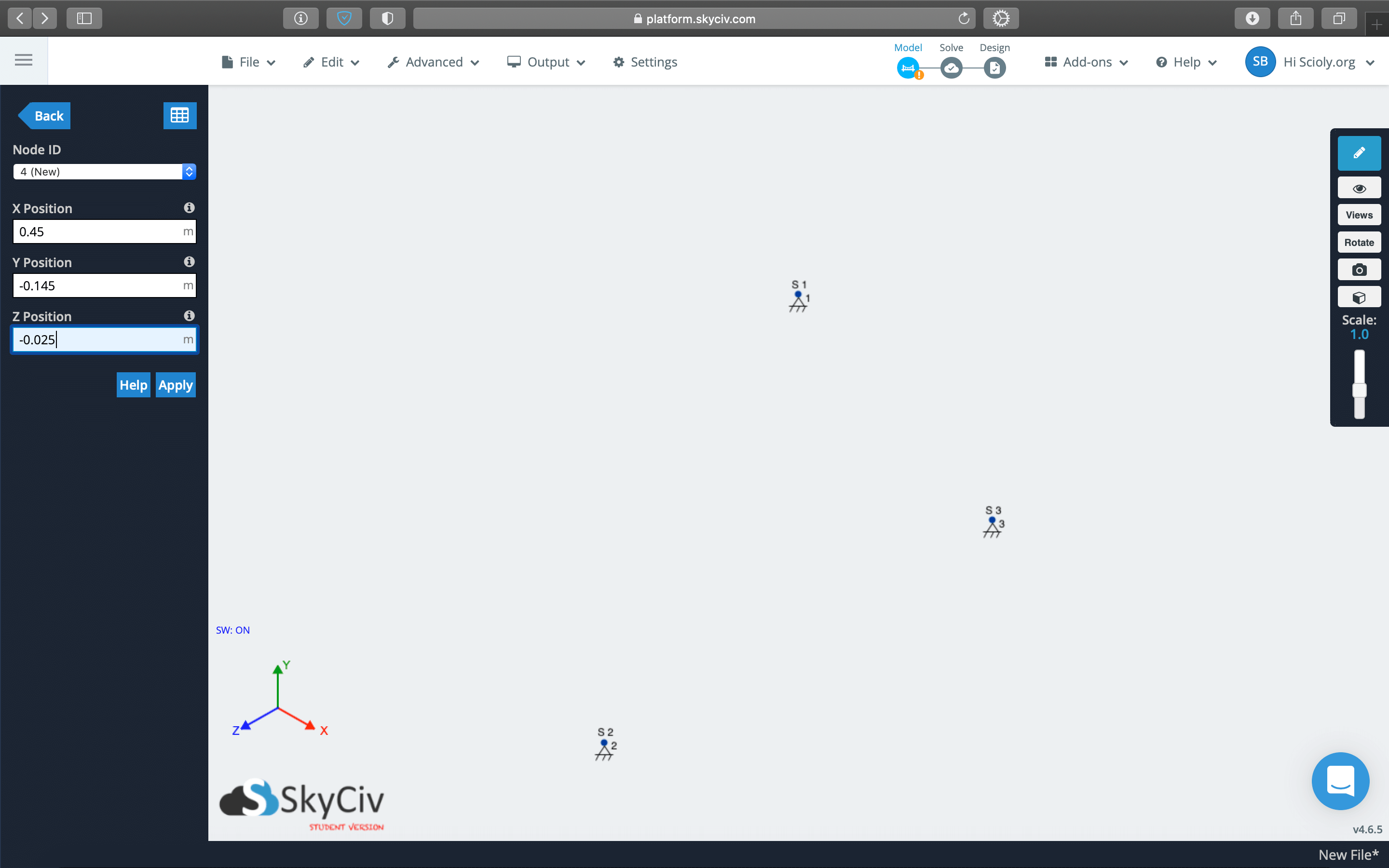
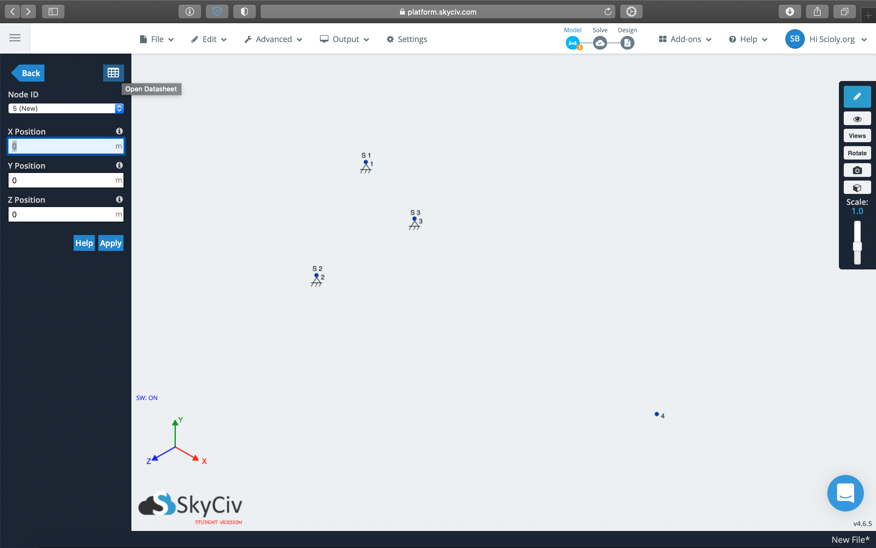
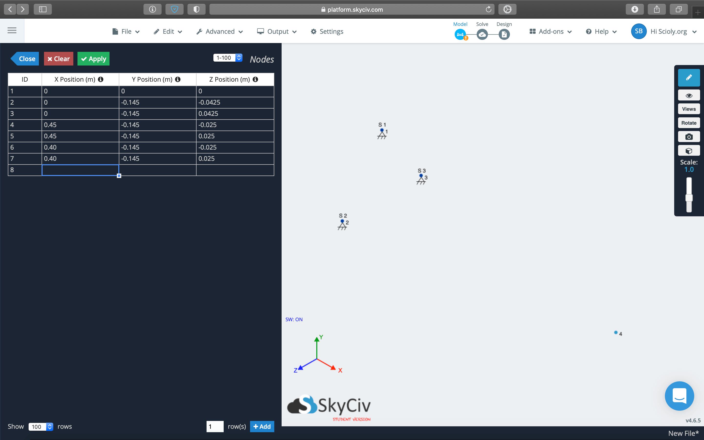
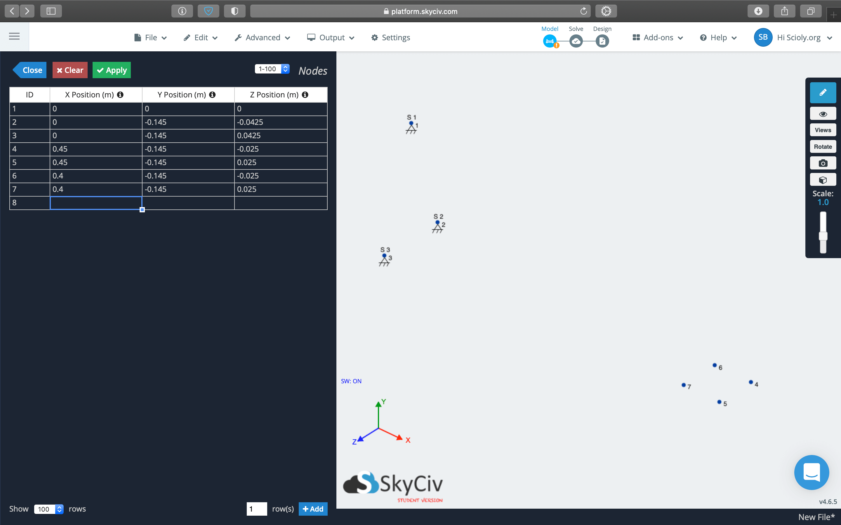
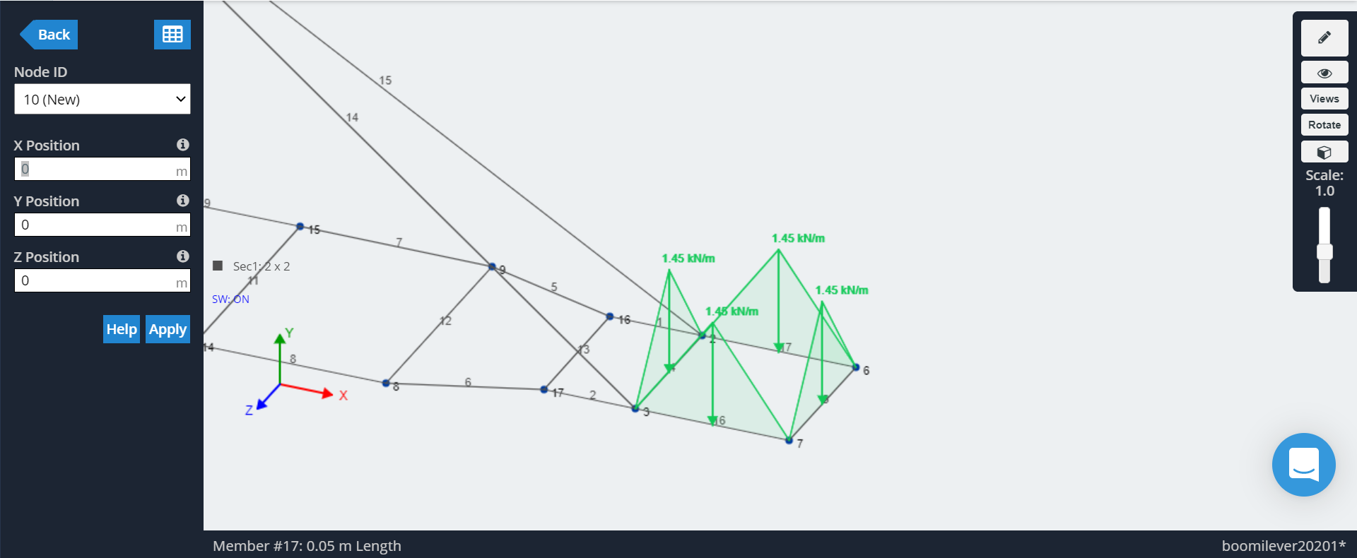
Nodes are the starting point (pun intended) for other components in S3D such as members and supports. They are defined with three coordinates in x, y, and z.
You can add your nodes individually by entering one node at a time or in bulk via the datasheet input, which also allows viewing the coordinates for all nodes. The datasheet input method can be more efficient for input or adjusting coordinates of many nodes in one go.
If you are using the Science Olympiad add-on, the add-on automatically defines three nodes as 3D Pin Supports, one for the Mounting Hook and two around the Contact Depth Line. You may move around these nodes to your desired location, just make sure they're not right on the edge of the Contact Depth Line or Contact Width Lines as those measurements take into account the size of each member—this is a common mistake!
Defining Members
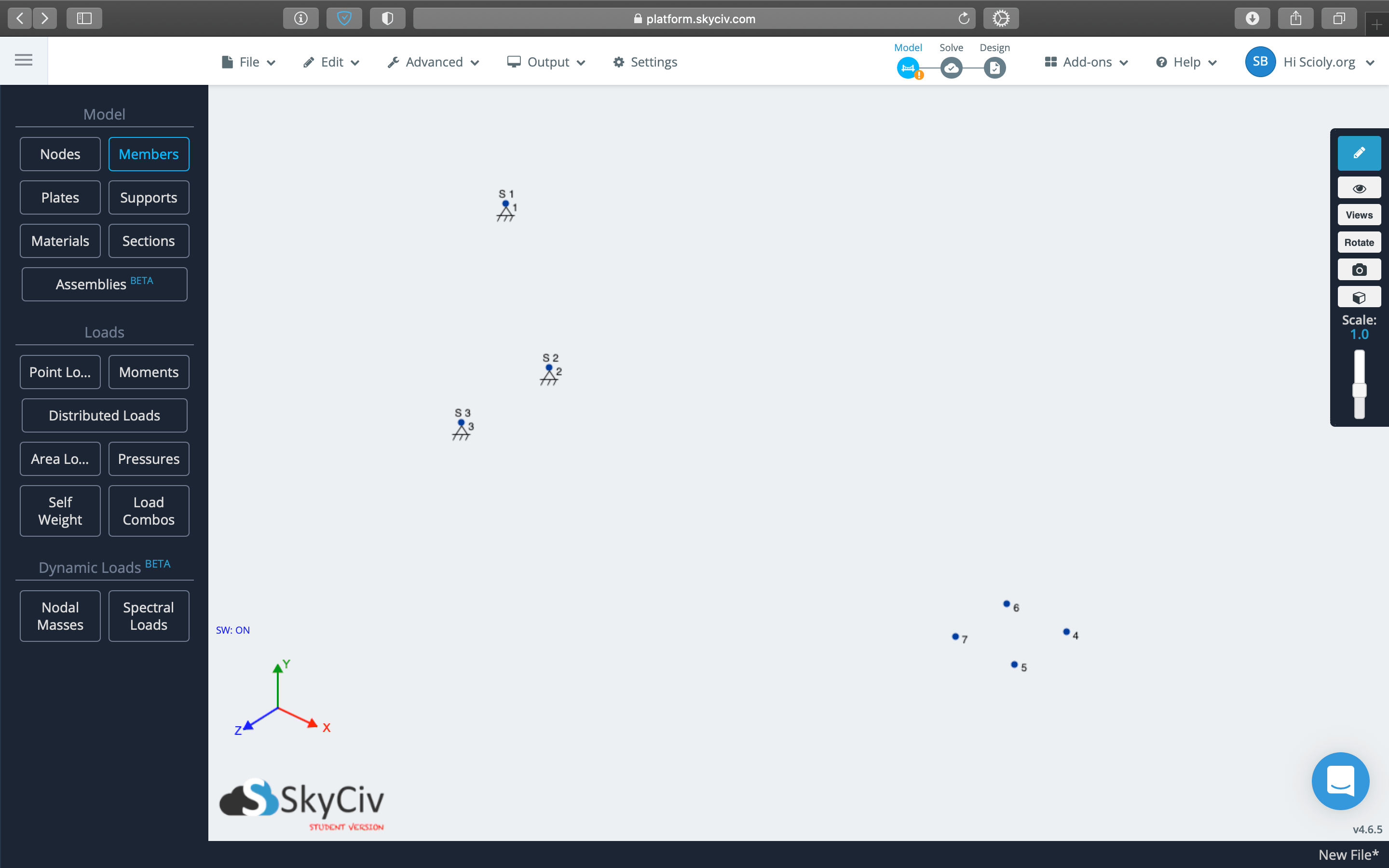
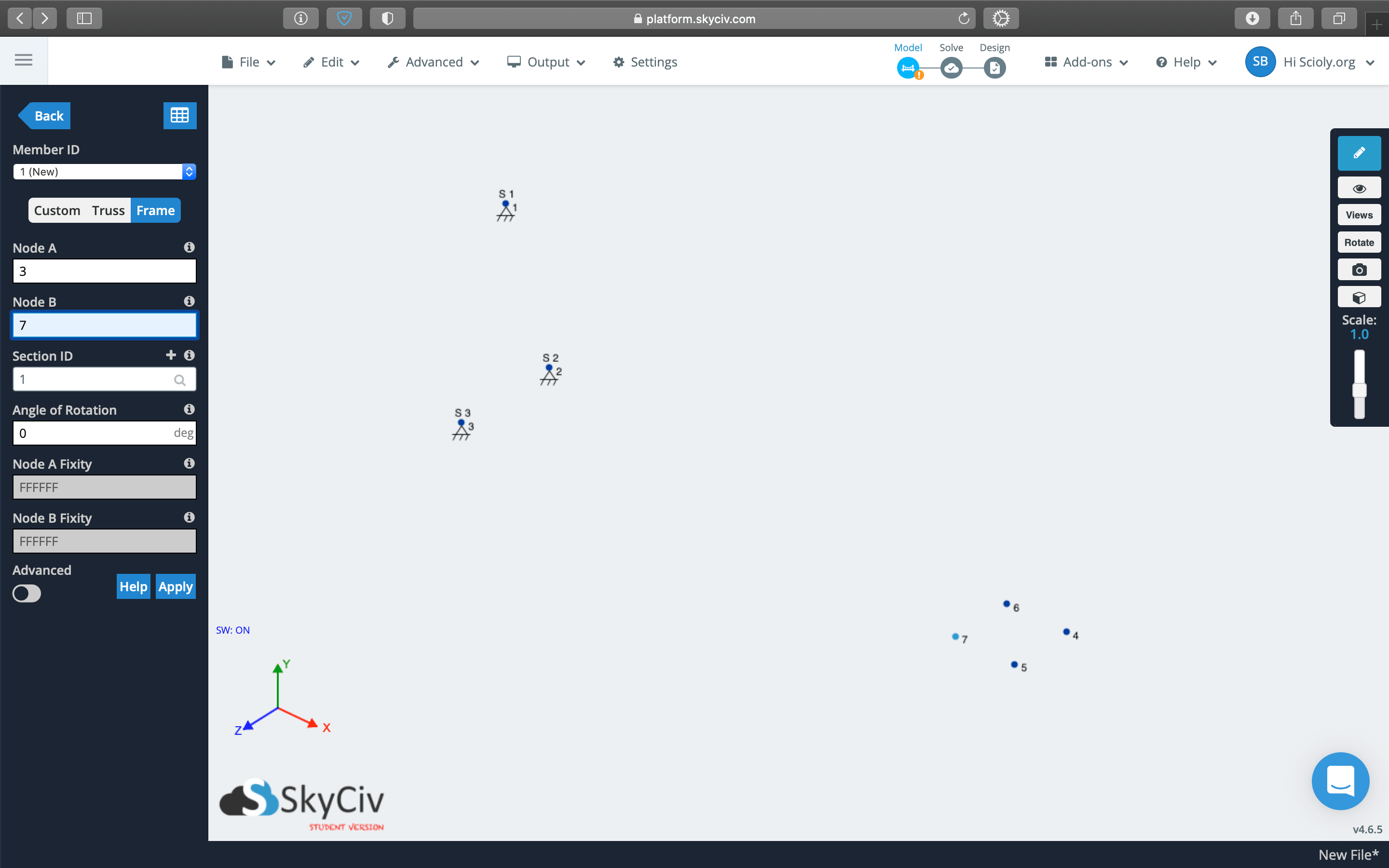
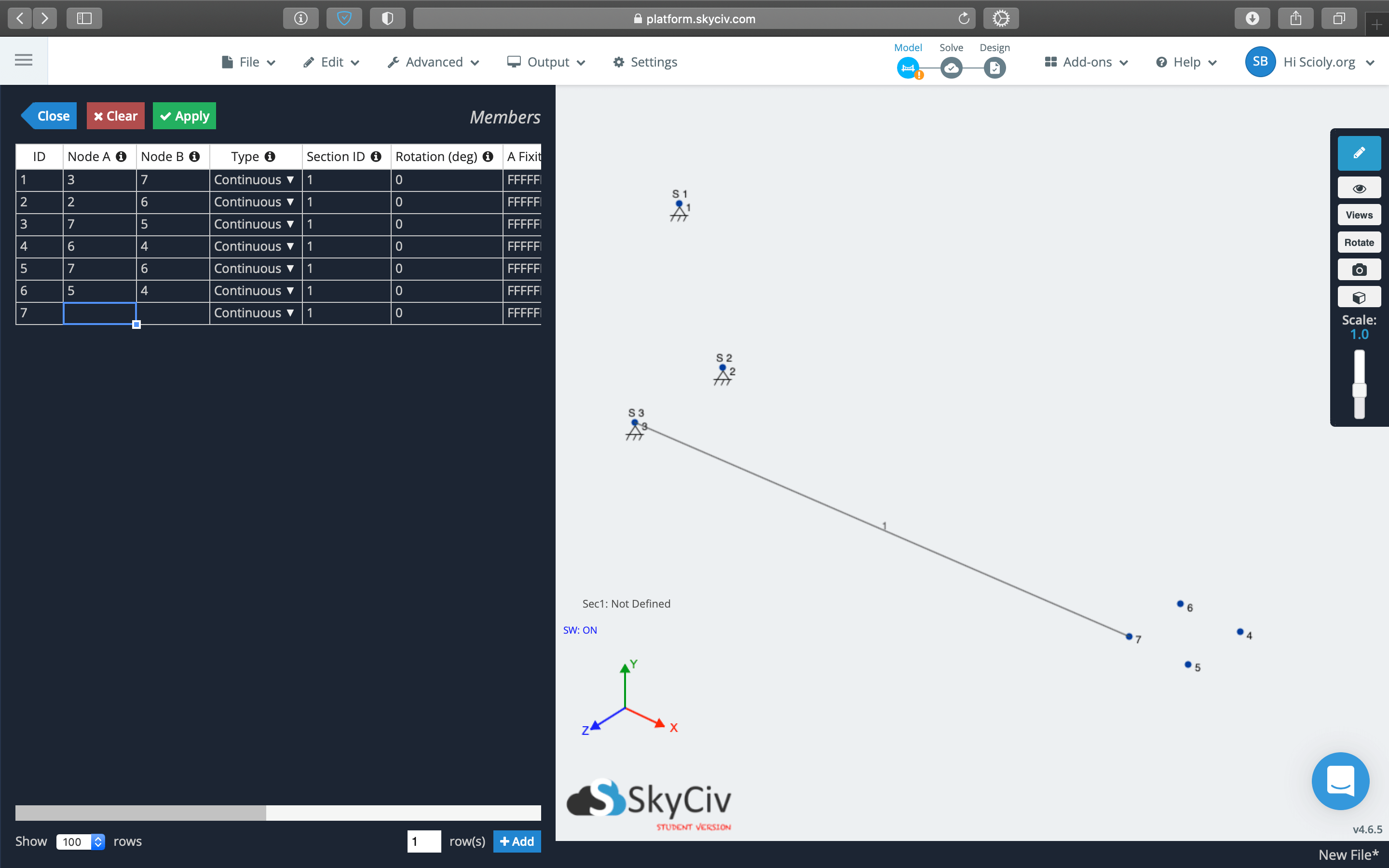
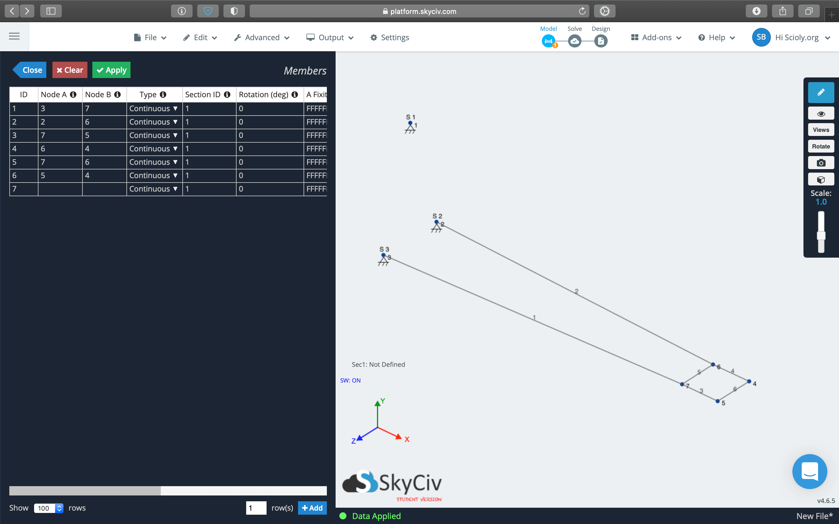
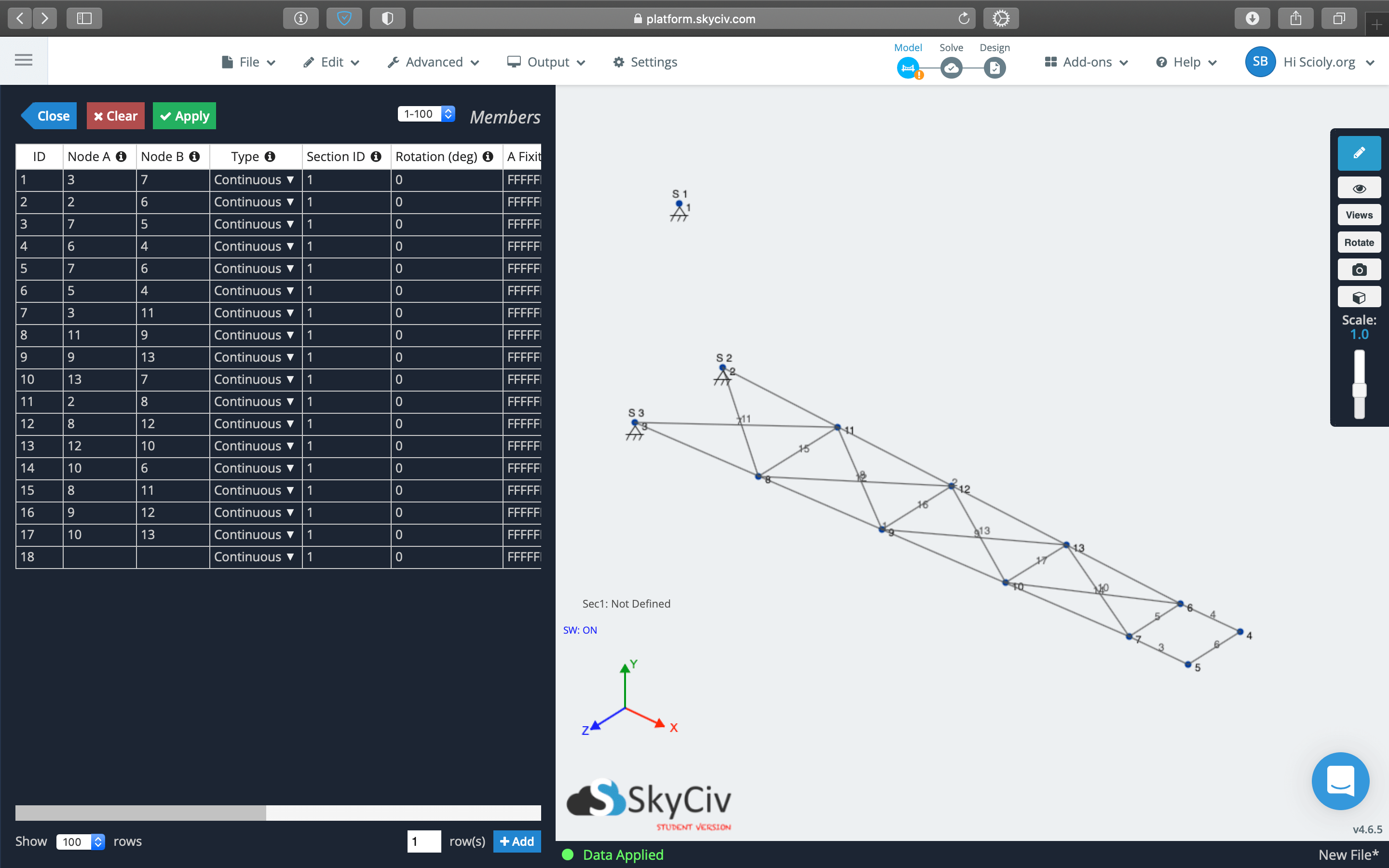
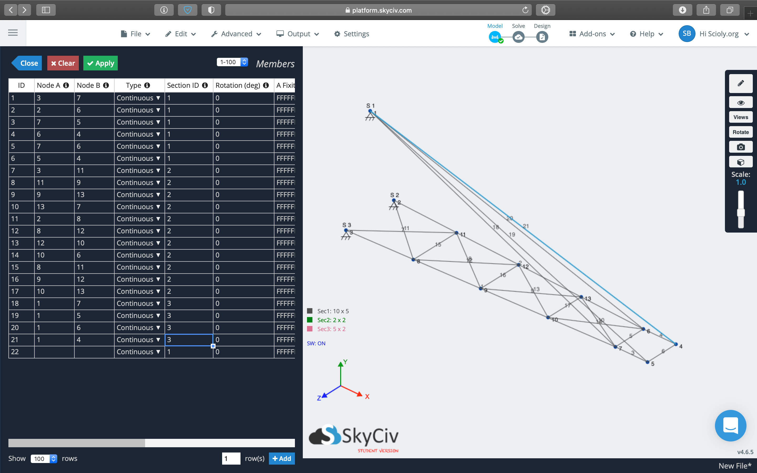
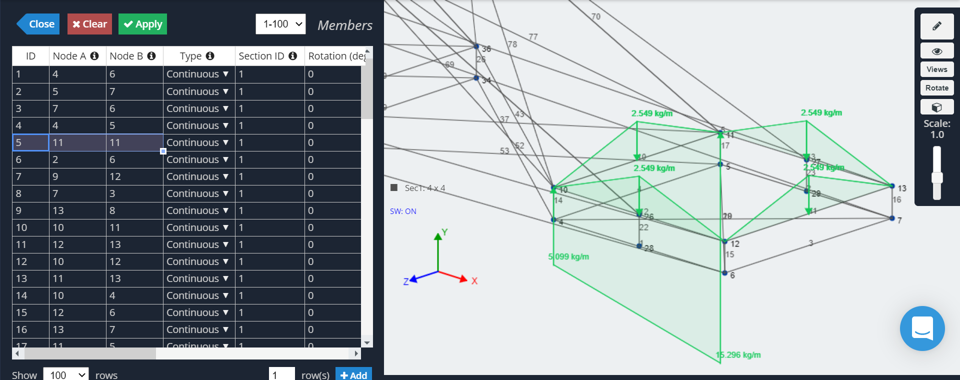
After defining nodes, you'll want to add members to connect them, simulating the sticks of a Boomilever! With the nodes defined, members are easy to add: just enter the numbers of the two nodes you want to connect. There are many options for members but the only ones you need to input are Node A and Node B (the pair of nodes to connect) and Section ID which is covered in the next section.
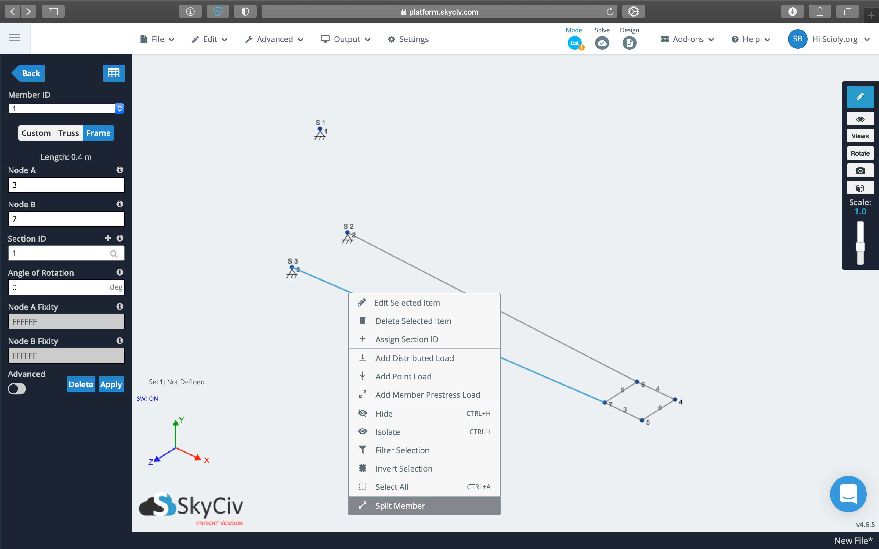
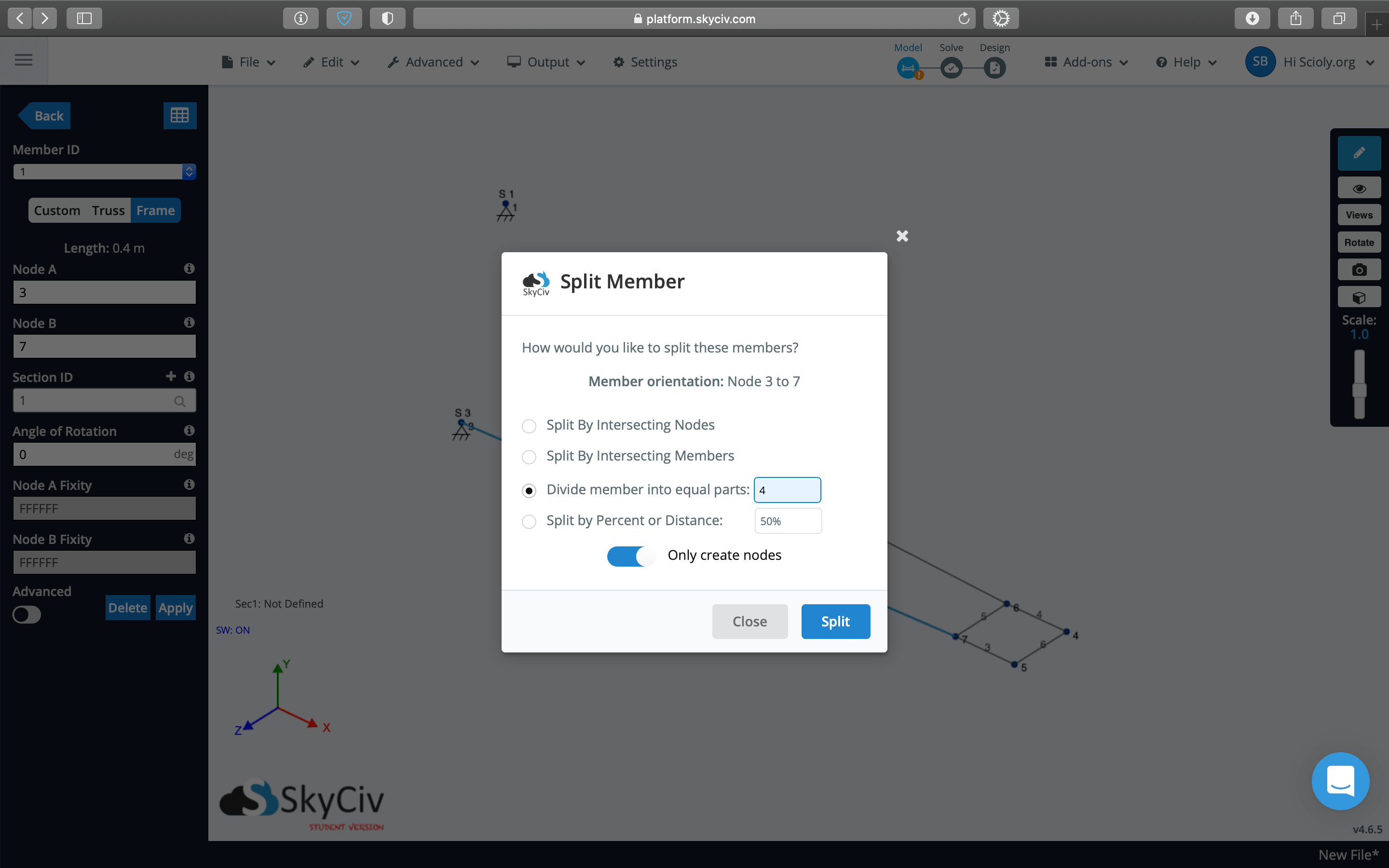
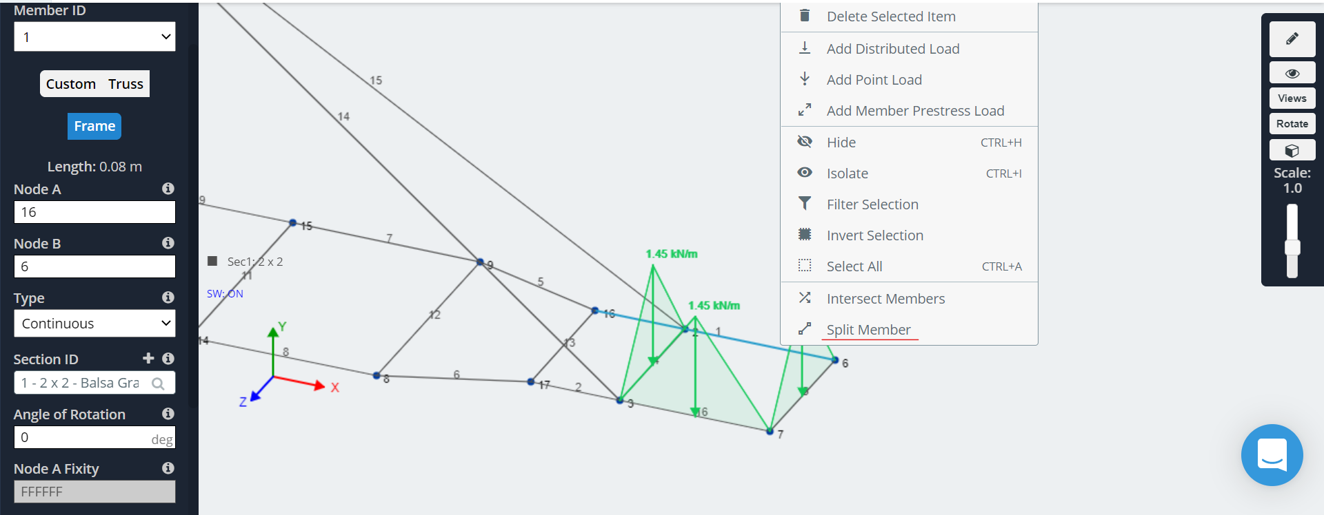
If you want to make many nodes along a line, for example to add bracing as shown below, you do not need to define each node individually and can instead use the "split member" tool! To split a member, you only need a member to split and the number of equal parts into which you want to split the member.
Defining Sections
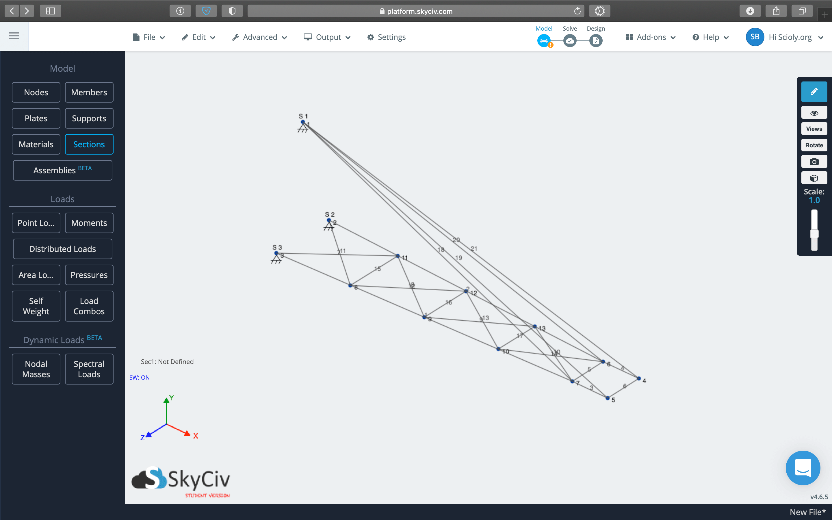
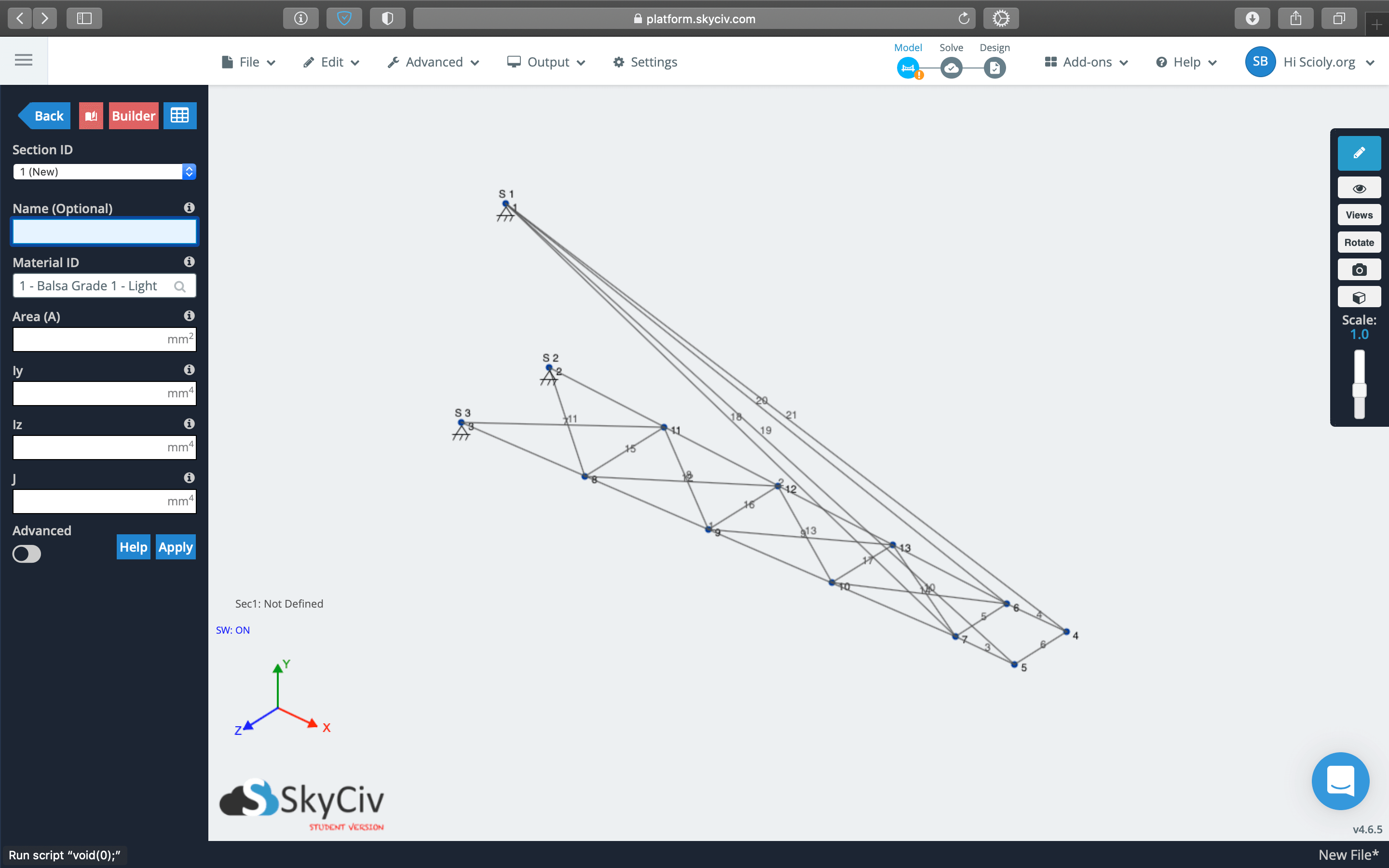
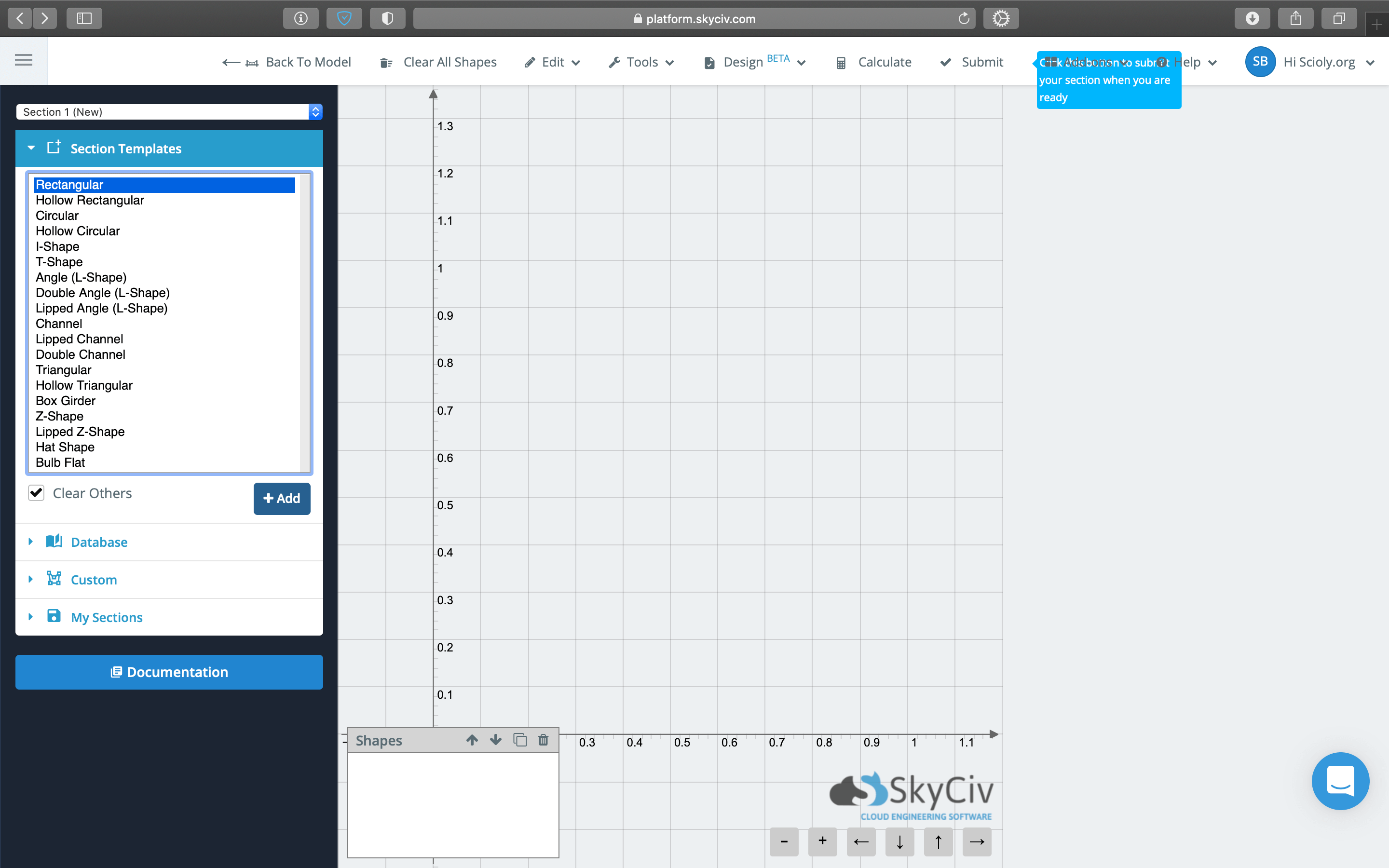
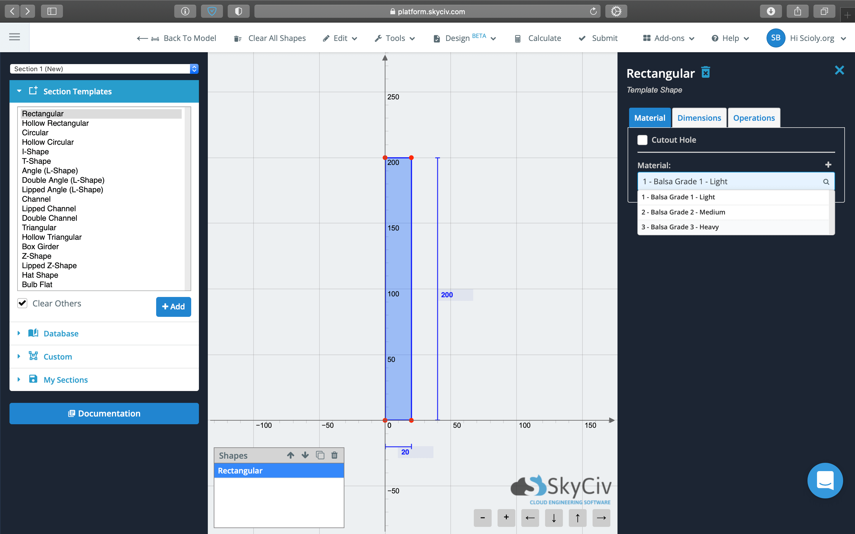
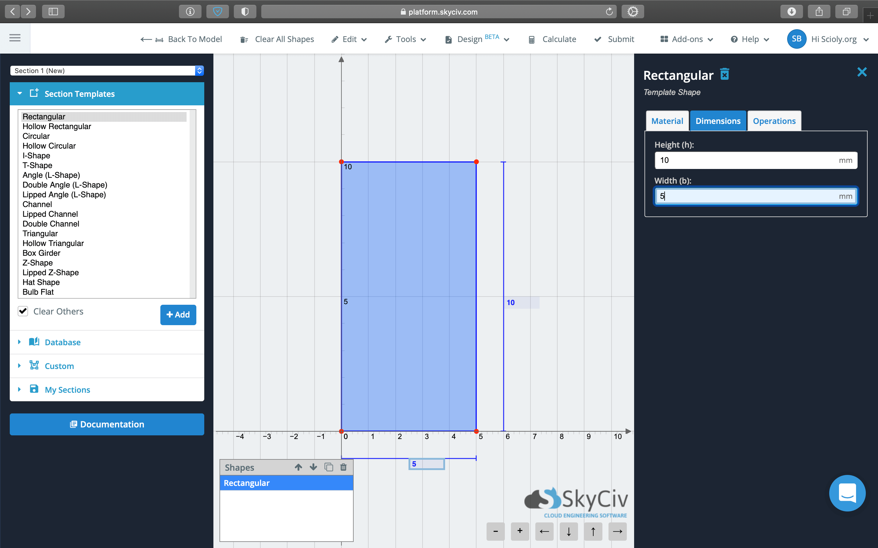
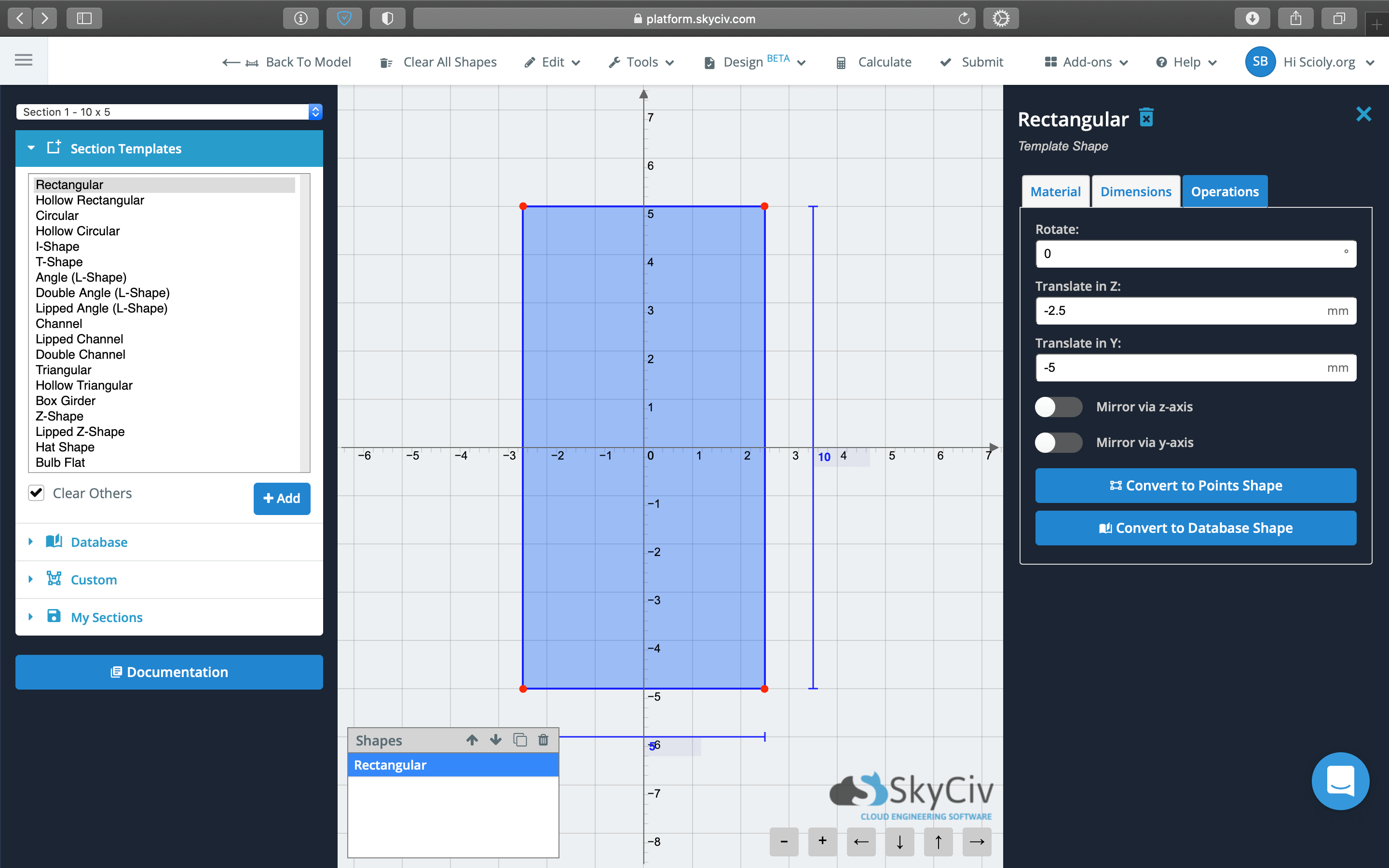
After adding members, you'll want to give them appropriate sizes with the sections tool. Adding sections requires a few more clicks but is rather straightforward: you set the geometry to rectangular, specify the width and thickness, and specify the balsa wood density—just like picking out wood at the hobby store!
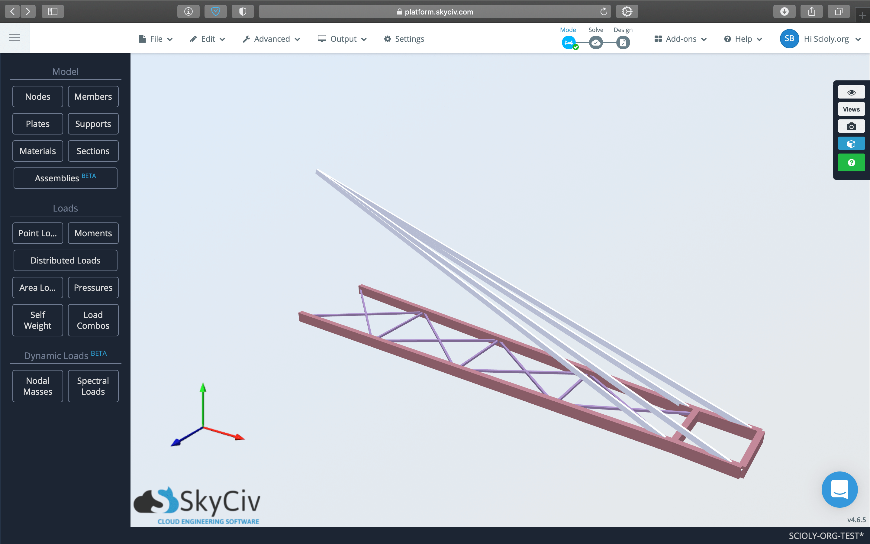
You can verify that you've entered reasonable section sizes by rendering your structure. This will allow you to see that you haven't accidentally entered a 0.05 m (5.0 cm) wide section instead of your intended 0.005 (0.5 cm)!
Defining Supports
Supports add physical restraints to your model. The pin support at the Mounting Hook fixes that end of your Boomilever at the hook and the two pin supports along the lower part of the Testing Wall fix your Boomilever against the wall. Without these supports, your Boomilever would have nothing to "grab" onto and would fall when loaded!
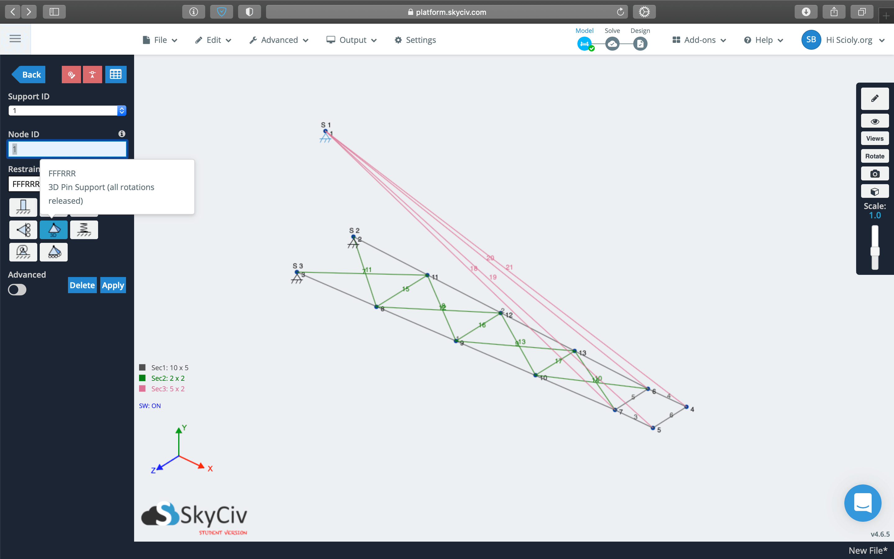
If you are using the Science Olympiad add-on, the add-on automatically defines three 3D Pin Supports, one for the Mounting Hook and two around the Contact Depth Line. You may move around these supports to your desired location, just make sure they're not right on the edge of the Contact Depth Line or Contact Width Lines as those measurements take into account the size of each member—this is a common mistake!
| Adding Supports | |
|---|---|
| Step 1 | Step 2 |
|
|
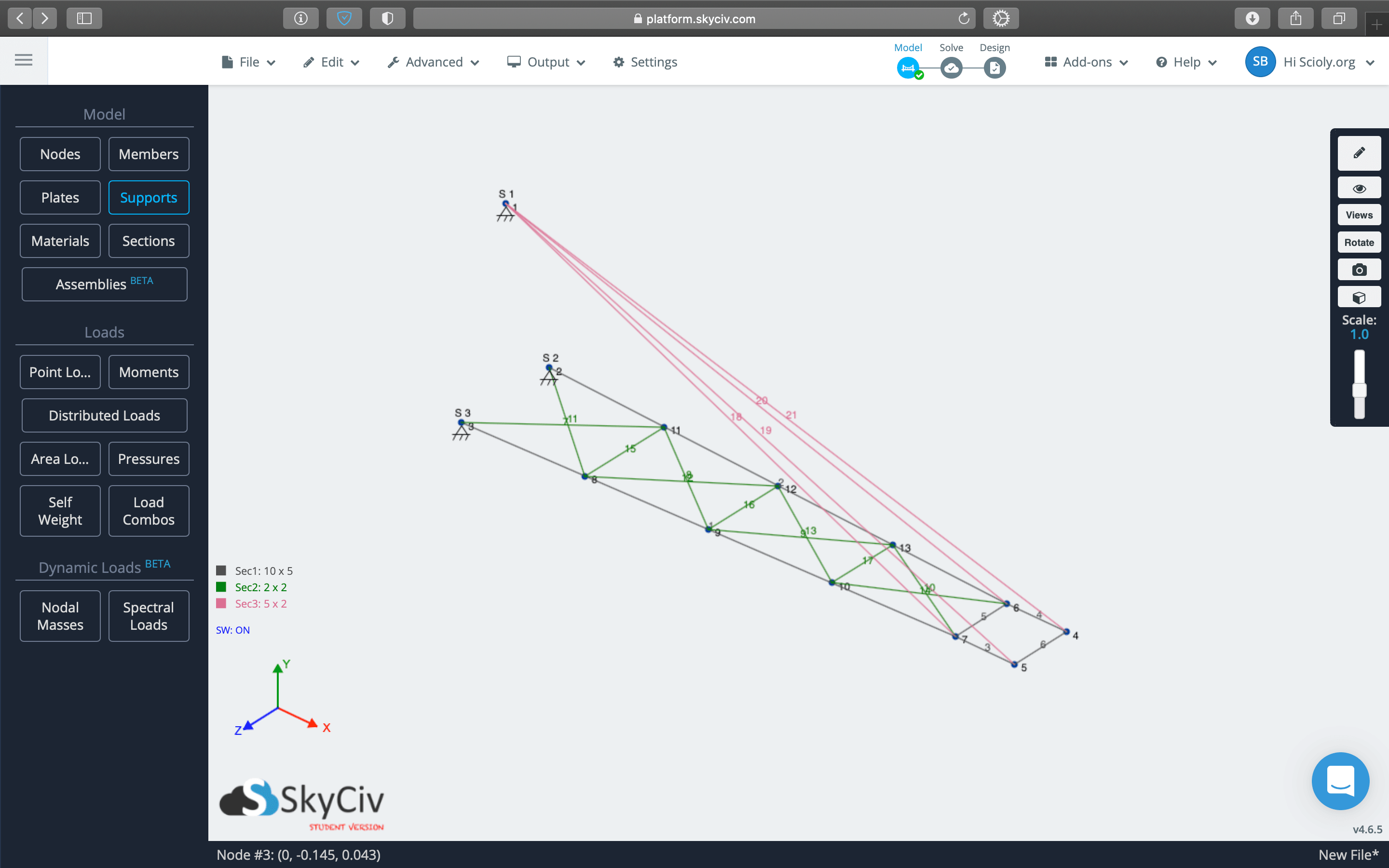
| From S3D, click on Supports in the left panel. | Specify the Node ID to which to apply the support and the support type. 3D Pin Support most accurately represents the contact between the Boomilever and the Mounting Hook or Testing Wall and is required by Digital Structures rules. Click Apply to define the support. |
Defining Loads
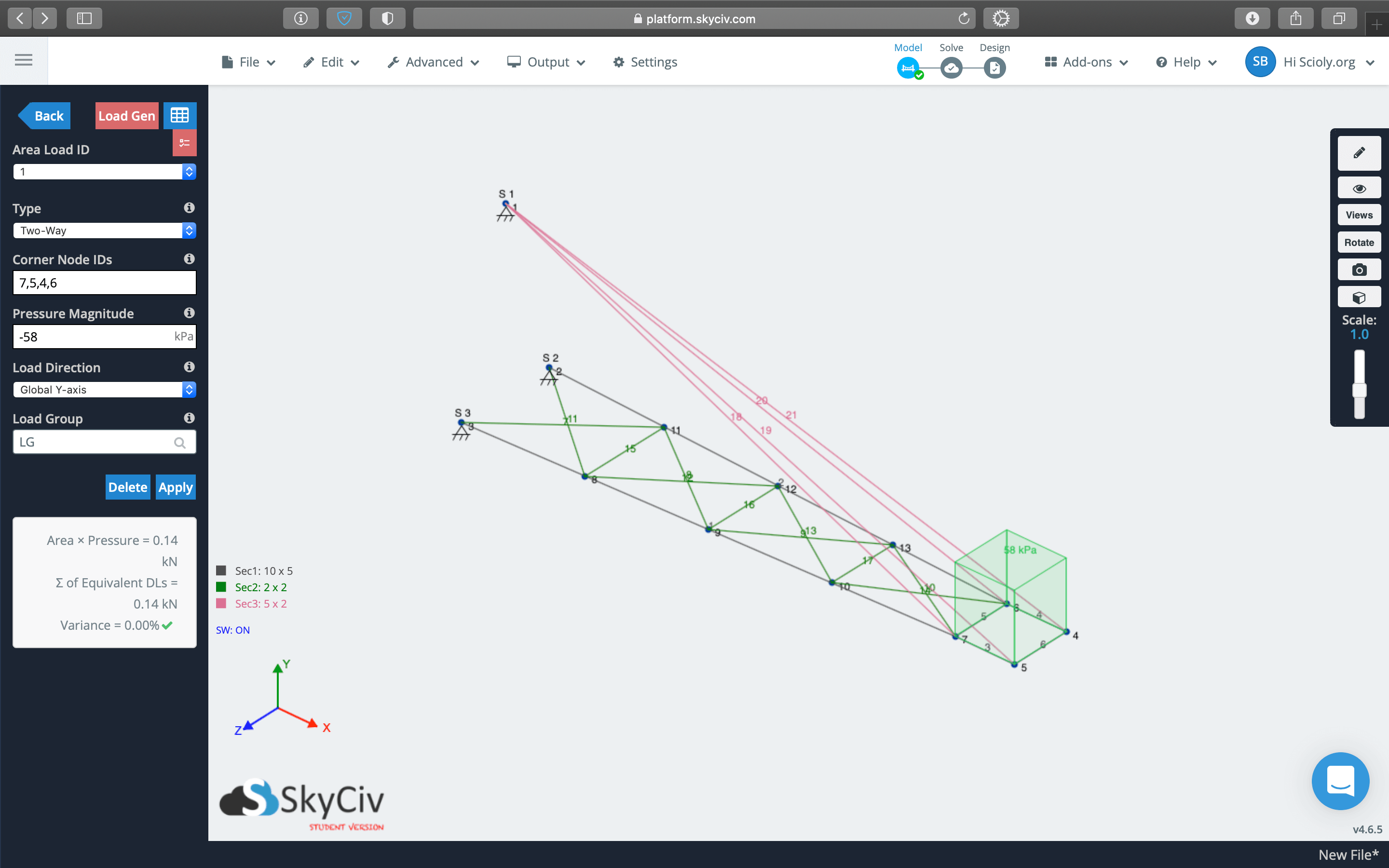
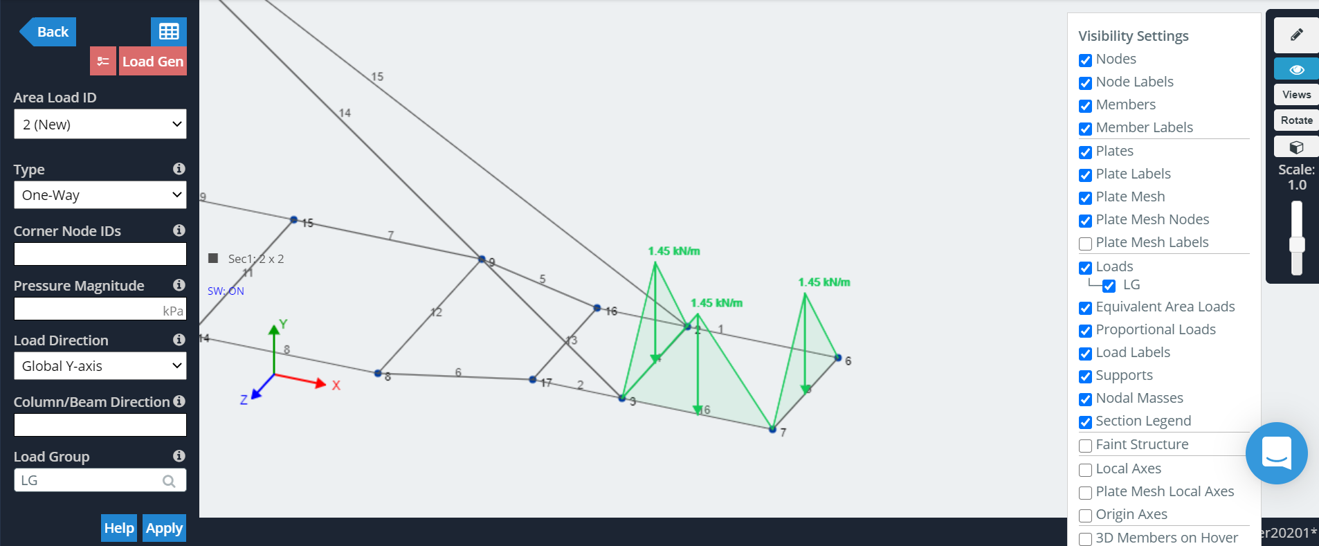
Loads tell the software where to apply a force on your structure, simulating you placing the Loading Block on your Boomilever, hanging a bucket, and adding sand. An Area Load is used because it accurately simulates the Loading Block spreading out the force of the bucket and sand over a 5 cm by 5 cm area.
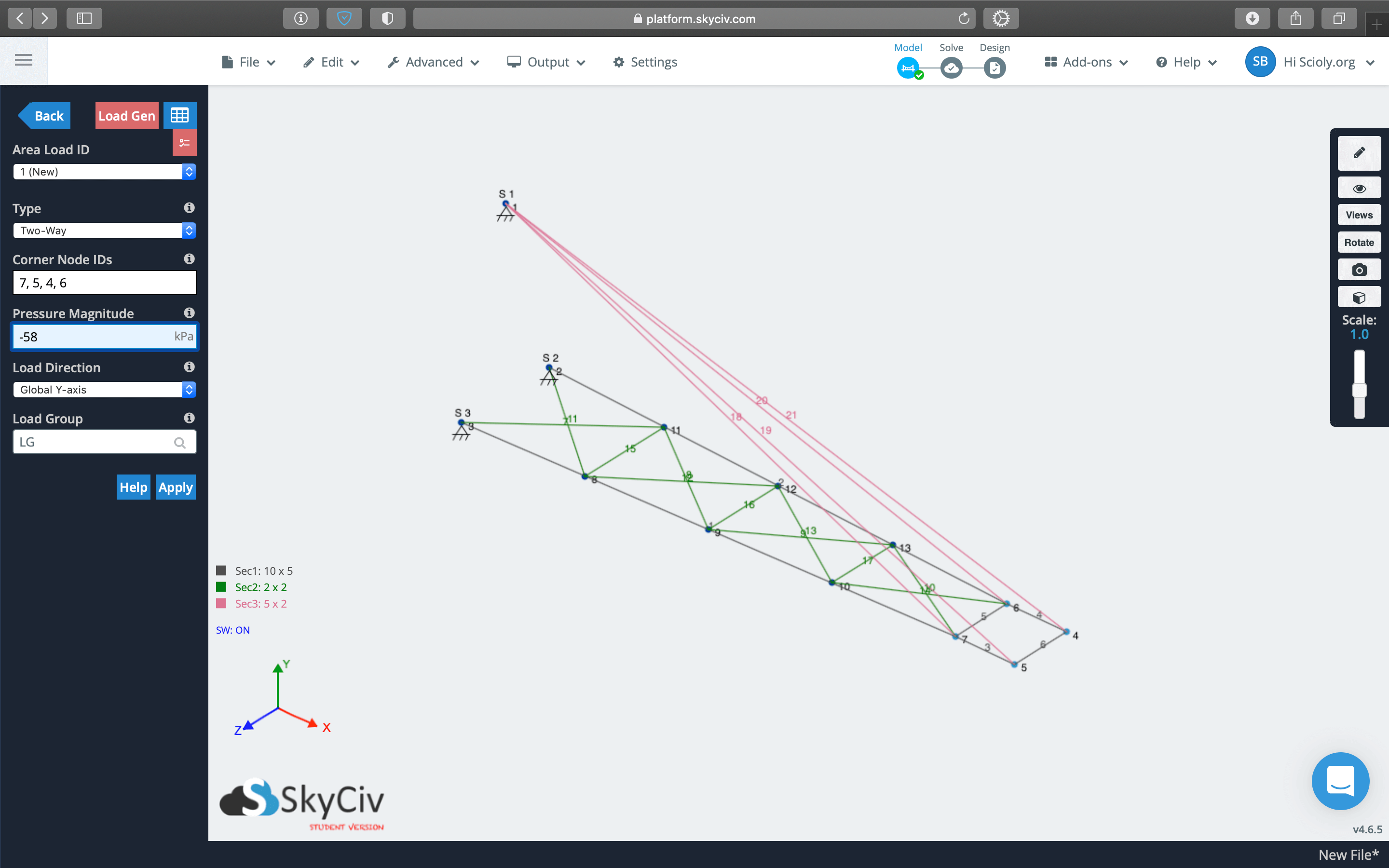
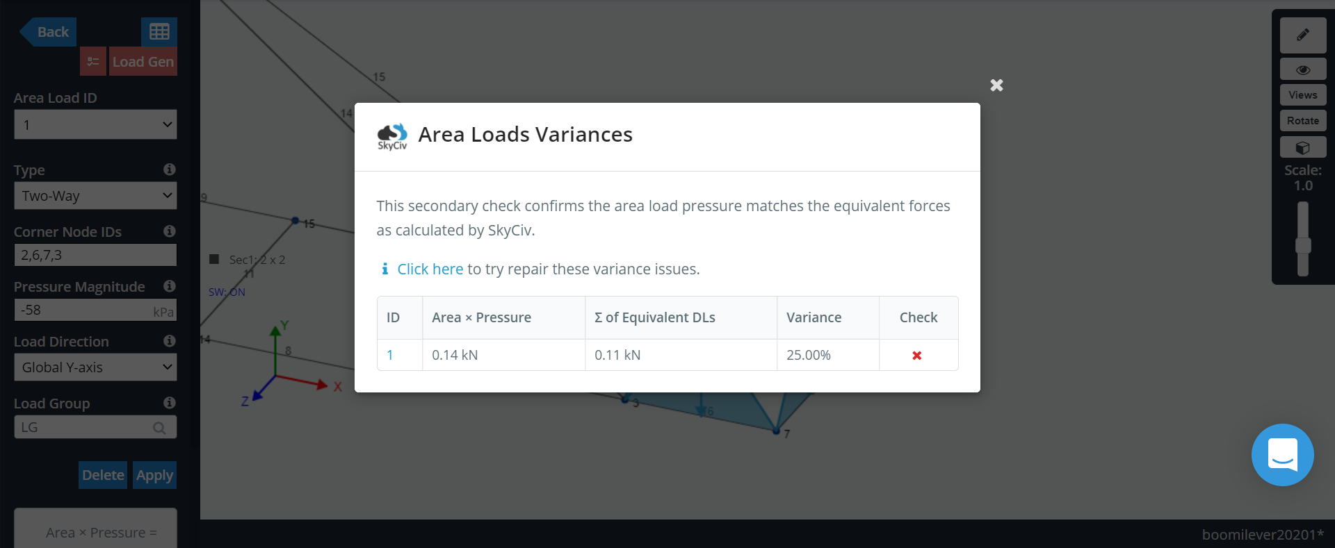
Before adding an Area Load, you will have needed to define four nodes at the corners of a 5 cm by 5 cm rectangle. To add the Area Load, specify the four Node IDs for the four corners to this rectangle in clockwise or counterclockwise order. Notice for the Boomilever pictured below, the order is 4, 5, 7, 6 and not 4, 5, 6, 7—this is a common mistake that will cause an error in testing! You'll also want to specify the Area Load as Two-Way and with magnitude -58 kPa. The negative sign tells the software to pull downward on your structure.
Rendering Your Structure
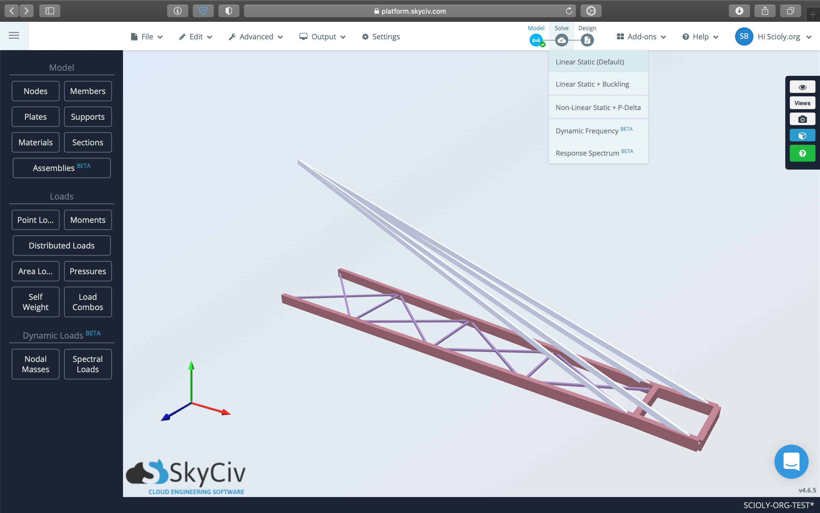
Rendering your structure is a quick way to verify that you've entered correct section sizes for your structure.
Testing Your Structure
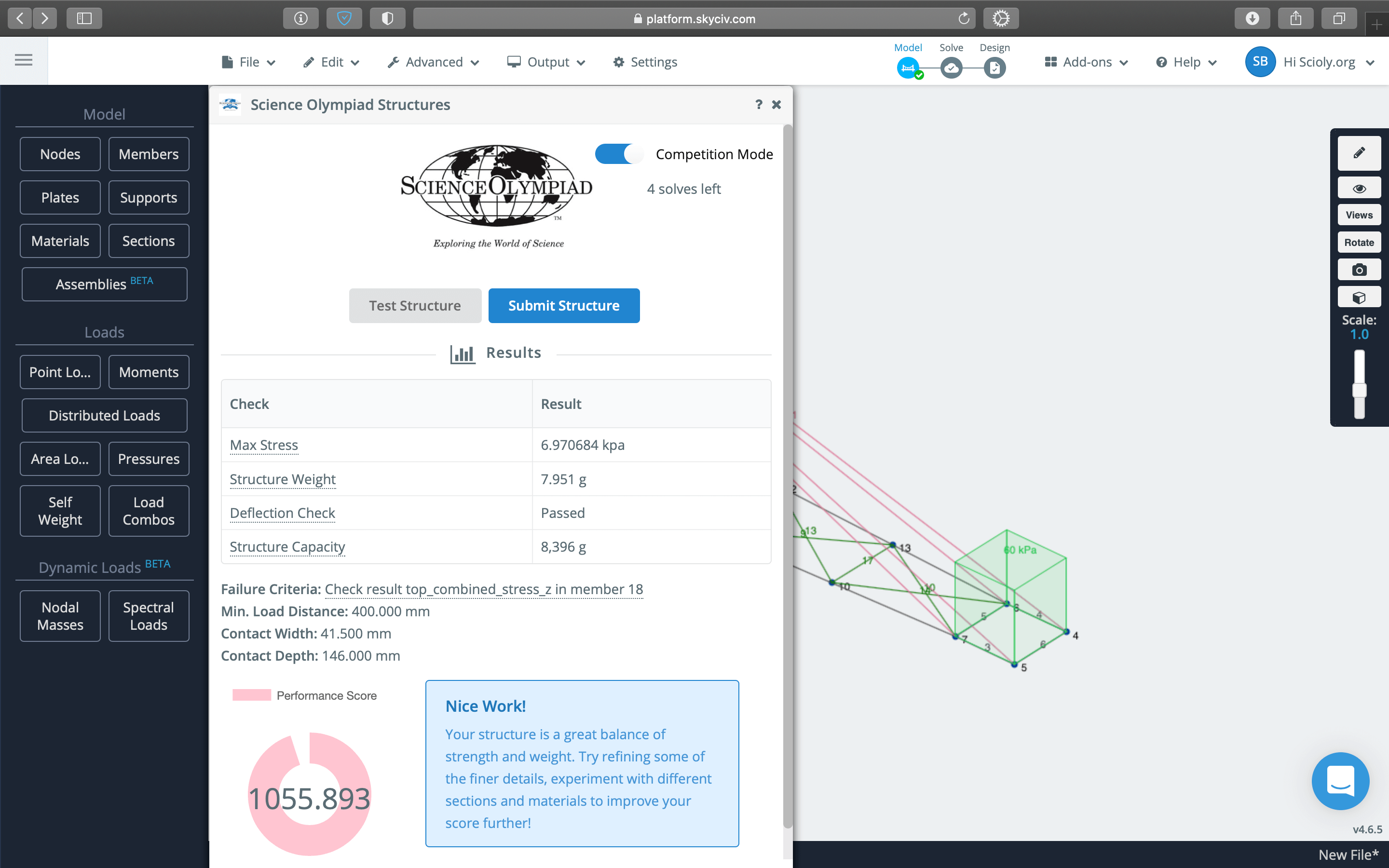
With nodes, members, sections, supports, and loads defined, your structure is ready to be tested! Open the Science Olympiad add-on from the Add-ons dropdown at the top right and click the Test Structure button.
The Science Olympiad Structures window will display the results of your structure, including its Structure Weight (Mass of Boomilever), Structure Capacity, and other construction measurements (Contact Width and Contact Depth). Be sure to check the Contact Width and Contact Depth against the specifications provided by the Event Supervisor to avoid Construction Violations!
If you are at a competition and have Competition Mode enabled, you'll be limited to only five tests and the last one is used for your submission.
Submitting Your Structure (For Competition Mode)
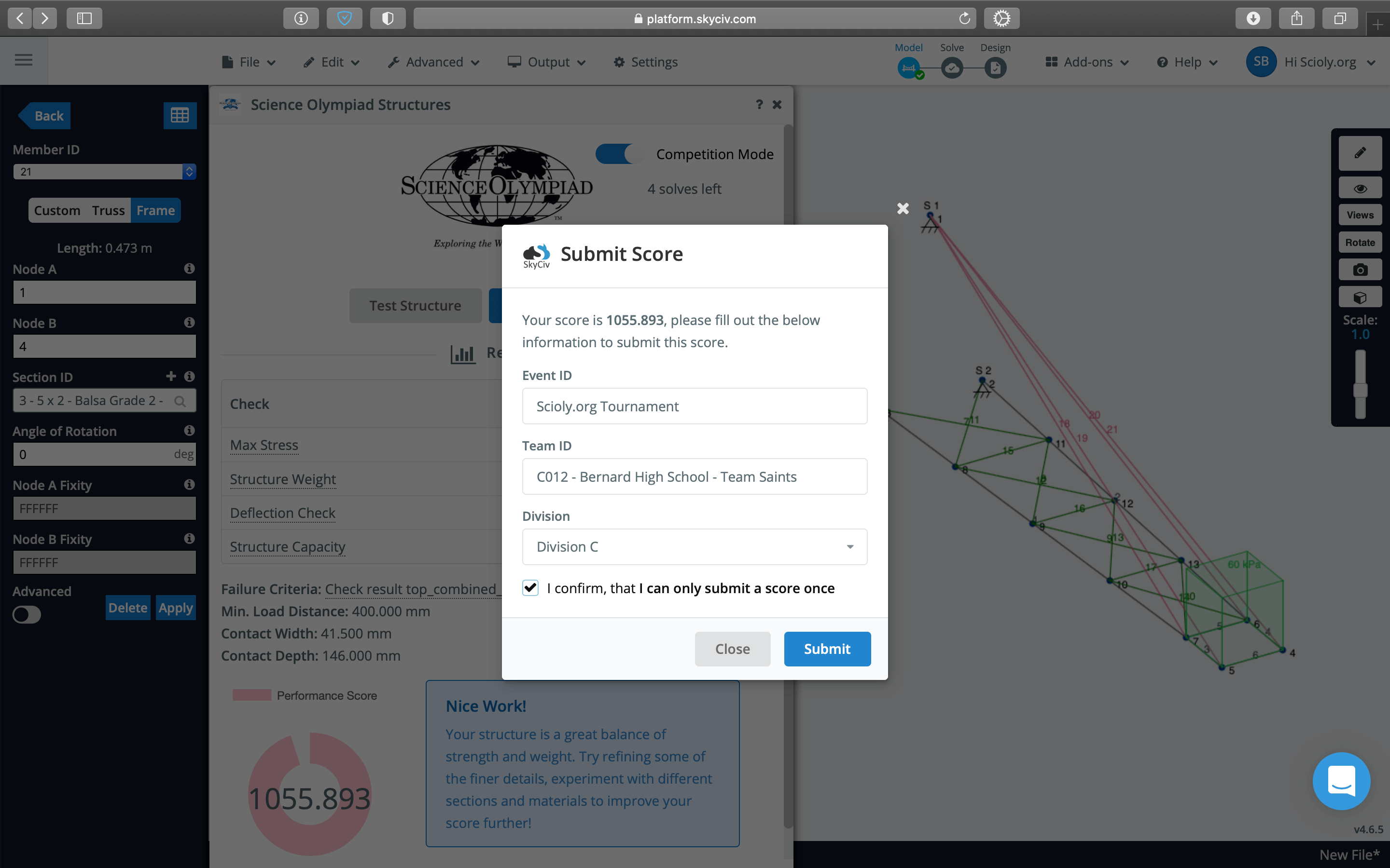
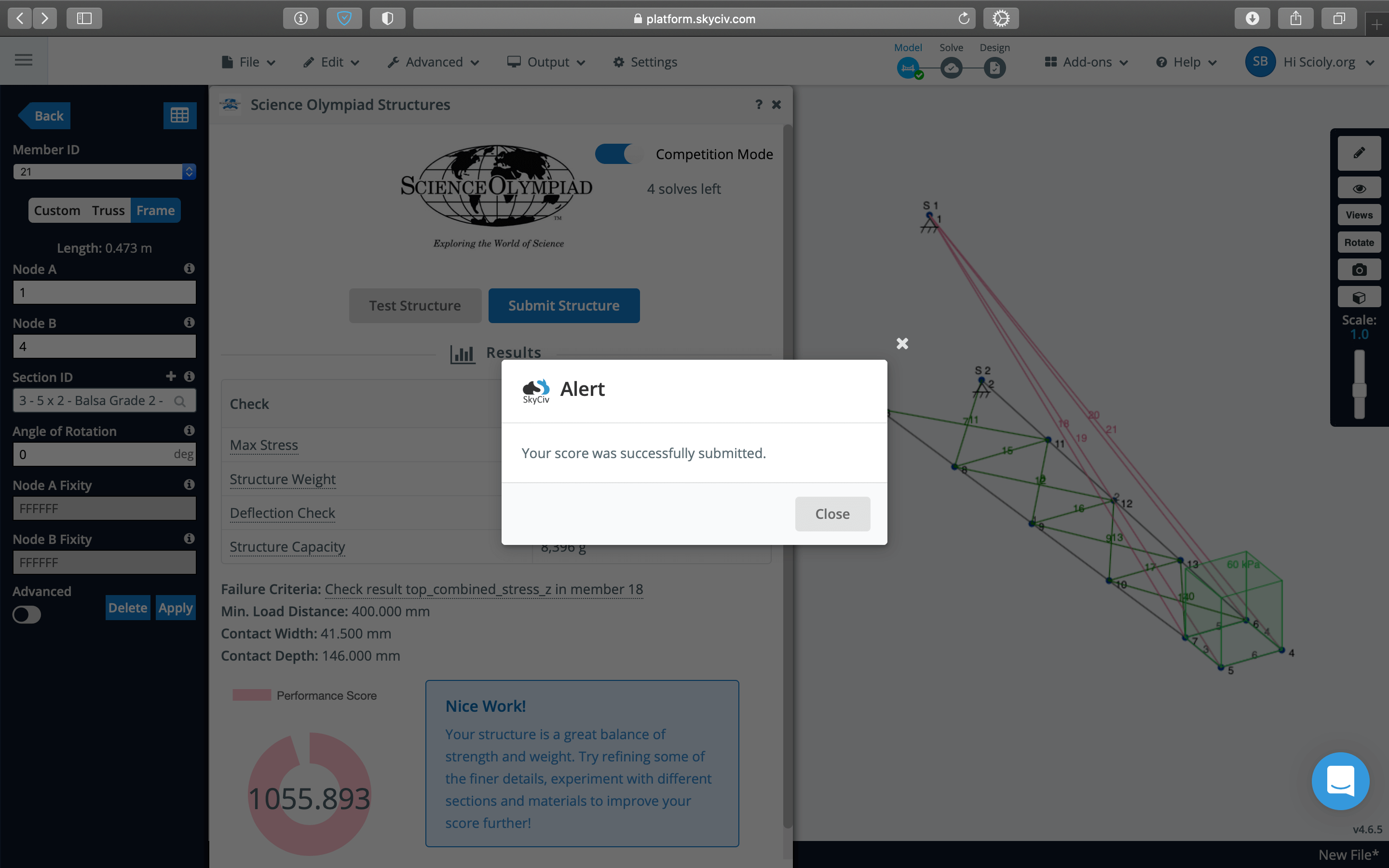
If you are at a competition and have Competition Mode enabled, you'll need to submit your work via the Submit Structure button for your score to be counted. Only one submission is allowed during the 48 hours that Competition Mode is active.
When entering your information, be sure to enter the correct tournament name for Event ID and enter all of your team's details (team number, school name, and team name) for Team ID. This will ensure your submission is correctly matched to your team and not missed!
Improving Your Structure
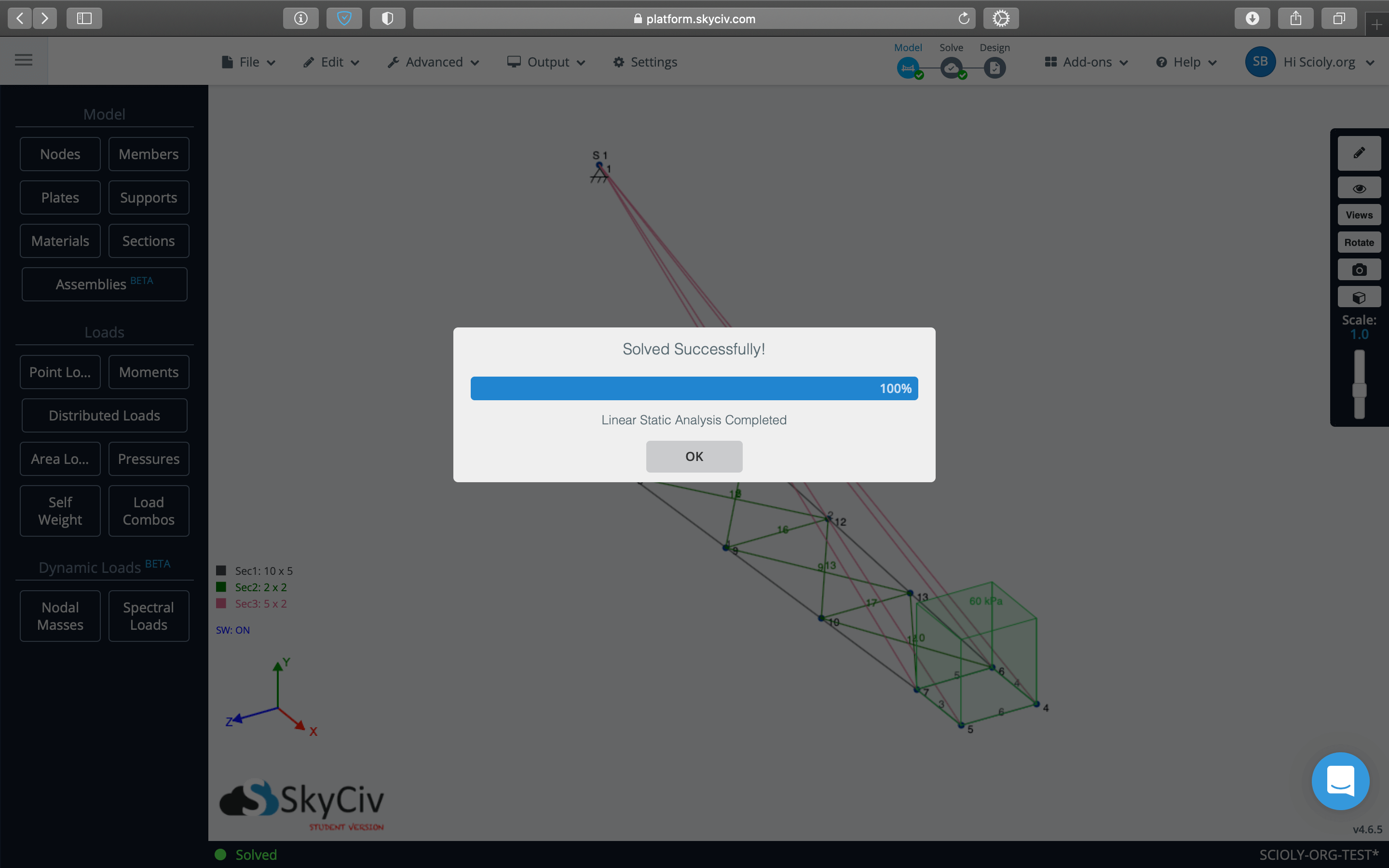
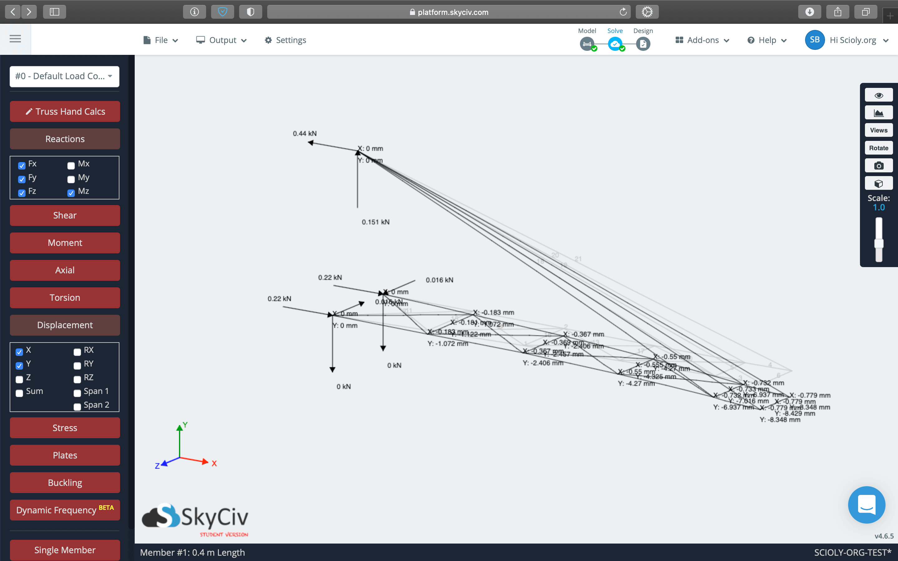
The S3D platform allows you to complete thorough analyses of your structure using the "solve" function. The results of a solve will show you where your structure experiences the greatest forces, which is useful information to have as unbalanced concentration of stresses is the cause for Boomilever failure!
With these results, you can modify your structure to improve its strength. You can adjust section sizes, add or remove members to see their effect on the structure, or change densities of members (through sections) to see how that affects strength. It's the usual design iteration you'd normally complete with a physical Boomilever, only a lot faster as you don't need to fully rebuild every time!
Common Mistakes
| Common Mistake | Explanation |
|---|---|
| Forgetting to design to the Contact Width and Minimum Loading Distance to specifications by the Event Supervisor | The rules for Digital Structures specify that the Contact Width and Minimum Loading Distance are to be announced by the Event Supervisor and therefore may vary from tournament to tournament. Check these values before you start building so that you can avoid Construction Violations! |
| Not checking measurements from the Science Olympiad add-on before submitting | After testing your structure, the Science Olympiad Structures window displays measurements recorded for your Boomilever. Check these values against those specified by the Event Supervisor so that you can avoid Construction Violations! |
| At competitions, forgetting to turn on Competition Mode before starting to build | Competition Mode clears your model when turned on, so if you forget to turn it on at the beginning, you'll have to redesign your model after it is turned on! |
| At competitions, forgetting to click submit on the Science Olympiad add-on | The only way a competition will know you competed in Digital Structures is if you submit your work. Please don't forget to submit! |
| Defining an Area Load with numbers out of order | Area Loads must be defined following the order of the nodes clockwise or counterclockwise around the boundary of the Area Load. This is not always the same as numerical order! Refer to the Defining Loads section above for an example. |
| Designing a structure that does not have a place for the Area Load | Without an Area Load, you can't test your structure or get a score! Be sure remember to design in the four nodes that are the corners to your 5 cm by 5 cm rectangular Area Load. |
| Using a Distributed Load instead of an Area Load | A Distributed Load is the wrong type of load to use for Boomilevers. In SkyCiv, distributed loads vary the force applied along a length; this means the force at different points along the load will be different! You want to use an Area Load, which evenly distributes the force across the entire area. |
| Forgetting to define the Area Load as negative | The Area Load needs to be negative to simulate the weight of Loading Block, bucket, and sand pulling downward on your Boomilever. |
| Adding extra 3D Pin Supports in places | You Boomilever should only have 3D Pin Supports at the Mounting Hook and where it contacts the Testing Wall near the Contact Depth Line and Contact Width Lines. Any extra supports restrain your structure unnaturally and may result in a Construction Violation. |
| Adding members that cross through the Contact Width Lines | Connecting the nodes that contact the Testing Wall with a member not only crosses the Contact Width Lines (a Construction Violation) but also provides your Boomilever no structural benefit as those points are already fixed in place by the 3D Pin Supports! |
Troubleshooting
Fixing an Area Load Variance Issue
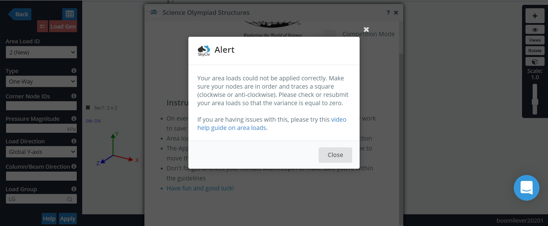
If the variance of your area load is not equal to 0%, this will prevent your structure from being tested.
For more detailed information, refer to SkyCiv's Video on getting the Area Load Variance to 0%. There could be other causes of a nonzero area load as well, so the best way to avoid this issue during a competition is by testing the base design beforehand.
Additional Resources
- Peter Hung's Computilever Tutorial for BEARSO
- How to Design a Boomilever by SkyCiv
- How to Test for Common Boomilever Failures by SkyCiv
- Science Olympiad Model Templates by SkyCiv
- SkyCiv Questions & Answers by SkyCiv on Scioly.org Forums
- Trial Event Rules for Digital Structures


