Electromechanical Relays
Electromechanical Relays
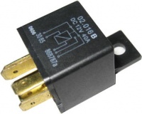
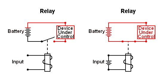
| Relays have many uses in any event involving electronics, such as Robot Arm or Robo-Cross. An electromechanical relay uses the magnetic field produced by an electrical current flowing through a coil to close one or more mechanical switches. |
A few uses for relays are:
1. Control a larger/smaller voltage/current with a smaller/larger voltage/current. 2. Holding or Latch circuit to “capture” a momentary input signal 3. As building blocks in basic logic circuits 4. Isolate the input circuit from the output circuit
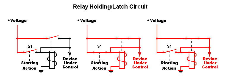
The Holding Circuit (or Latch) has commonly been used in MP to turn on a device with a momentary signal. A brief electrical pulse actuates a holding circuit which keeps power applied after the pulse has ended. For discussion, we’ll use a ball rolling into an elevator to be raised to the top of the device. As the ball enters the elevator, it depresses a lever closing normally open contacts of a switch mounted on the floor under the elevator. As the elevator rises, it lifts the ball off the switch, releasing the lever and allowing the contacts to open. The drawing below shows the basic holding/latch circuit. To simplify the diagram, both the relay coil and Device Under Control use the same battery.
First Diagram: Electricity cannot flow to the Elevator (Device Under Control) because of the normally open contacts of switch (S1) and the relay. Second Diagram: The ball rolls into the elevator, closing S1, energizing the relay coil and starting the elevator. Third Diagram: The elevator lifts the ball off S1, allowing its contacts to open. Normally this would break the circuit and the elevator would stop; however, the closed relay contacts continue supplying current to both the relay coil and the elevator.
This works great, but sooner or later the elevator reaches the top. If it continues to run, it could cause physical damage or waste energy from the batteries. Our next circuit addresses the problem.
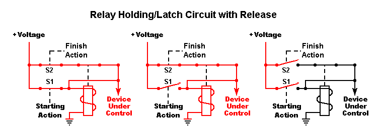
In this circuit we’ve added a normally closed switch (S2). Its purpose is to stop the elevator when it reaches the upper limit of its travel.
First Diagram: The ball has just rolled into the elevator closing S1 and starting the elevator. Second Diagram: As the elevator rises, S1 opens, but the latch circuit keeps the elevator on. Third diagram: When the elevator reaches the top, it opens the normally closed switch S2, de-energizing the relay and stopping the elevator. Since the relay contacts are now open, closing S2 will not start the elevator again.
A switch that prevents a device from exceeding specified parameters is called a “limit switch”, regardless of what type it is. Lever switches and magnetic reed switches are particularly well suited in these applications.
The Loop-Back Circuit And finally, the last circuit! Sometimes it’s desirable to have several devices in series. The circuit below shows how each device can turn off the preceding device. This is sometimes called a “loop-back” circuit.
Switches S1, S2 and S3 and the normally open relay contacts prevent any of the devices from running.
A mechanical action closes switch S1, energizing the 1st latch, starting the 1st device.
1st device continues operation, even though S1 has opened.
The 1st device completes, closing S2, energizing the latch, turning off the 1st device and starting the 2nd device.
2nd device continues to operate, even though S2 has opened.
 2nd device completes its action closing S3, energizing the 3rd latch, turning off the 2nd device and starting the 3rd device.
3rd device continues to operate, even though S3 has opened.
3rd device completes its action, openings S4, releasing the latch and stopping the 3rd device. Since none of the relays are latched, none of the devices will operate, even if S4 closes again.
Next: Add a circuit to return the elevator to the ground floor after the ball leaves the elevator at the top.


