Motor Speed Control

Locked
brian9640
Member
Member
Posts: 80
Joined: April 11th, 2016, 9:14 am
State: OH
Has thanked: 2 times
Been thanked: 24 times

Motor Speed Control

Post by brian9640 »

I have received a few questions about the robot's movements not always moving correctly like jumping or not rotating at the same speed. To help understand a possible cause, I created a few images below to help explain the motor issues.

Some issues are caused by the robot's program just setting the motor speed for a period of time. For the example below, the motor speed is set to 75% of the motor's full speed for a couple of seconds. In the graph below, the blue line shows the motor commanded speed at 75% for a period of time. The red line shows what motor's speed is more likely to be. This is because the robot as mass and physics is in play.

Image

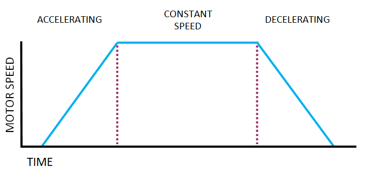
The robot's movements should follow the standard acceleration and deceleration curve show below. The motor speed should be increased following a defined acceleration. Hold constant speed then start to decelerate the motor at a defined rate.

Image

While the goal is for the motor speed to follow the ideal curve shown above, it is very unlikely to follow the curve perfectly. Again physics are involved. The graph below shows the more likely motor speed. The motor speed (red line) is much closer to the ideal curve. The closer the motor speed is to this blue line, then the more likely the left and right motors will move together and in a straight line.

Image

A common question is: How does one see exactly how the motor is moving? I recommend graphing your motor's movements to answer this question. The Arduino IDE has a tool for graphing output from the Arduino boards. The Serial Plotter is good tool that can create this graph. Below is an example of a robot's movement using the Serial Plotter tool. The grey line (speedProfile) is the ideal accel / decel curve. The blue line shows the actual motor movements. This graph can be used to improve your robot's movements.

Image

The above graph is from the TopFinishKits sample program V2.1. This new version was improved for the Serial Plotter tool and was just uploaded to the website.

Other items to consider:
  • Longer acceleration or deceleration times will improve the accuracy of the movement, but take longer to execute the moves.
  • Shorter acceleration or deceleration times make faster movements, but are more difficult to follow the ideal curve.
  • Driving in a straight line depends on all motors rotating at the same speed throughout the movement.
  • Remember the goal is for both motors to rotate at the same speed. If both motors actual speed match throughout movement, then following the ideal curve closely is not needed.
  • The accel / decel curve shown are basic movement curves. More advanced curves will use a "S-Curve". Which is outside the scope of this topic.
These users thanked the author brian9640 for the post:
bobbbbb (November 30th, 2023, 6:16 am)
User avatar
Sapphire
Member
Member
Posts: 44
Joined: April 15th, 2019, 4:52 pm
Division: C
State: MI
Has thanked: 2 times
Been thanked: 6 times
Contact:

Re: Motor Speed Control

Post by Sapphire »

I currently use a trapezoidal motion profile but see some skidding at higher speeds. Would you say an s-curve is the next step?
Pioneer High School
brian9640
Member
Member
Posts: 80
Joined: April 11th, 2016, 9:14 am
State: OH
Has thanked: 2 times
Been thanked: 24 times

Re: Motor Speed Control

Post by brian9640 »

Sapphire wrote: December 13th, 2023, 1:09 pm I currently use a trapezoidal motion profile but see some skidding at higher speeds. Would you say an s-curve is the next step?
S-curve can help. Reducing acceleration/deceleration rates and taking longer to accel/decel should have a larger impact on skidding.
a78099
Member
Member
Posts: 1
Joined: February 14th, 2024, 11:04 am
Division: C
State: NC
Pronouns: He/Him/His
Has thanked: 0
Been thanked: 0

Re: Motor Speed Control

Post by a78099 »

Hello,

Our team has decided to use the V2.1 sample program for our robot. We have a custom chassis but have the same motor, and we have changed the according variables to our robot's wheels and encoders. We understand that the robot uses an untuned PID curve, and we understand how it works. Without out, the target speed differs inconsistently from the actual speed. However, we are struggling to figure out how to use the serial plotter function as demonstrated in your post. We have analyzed both versions of the code, but the only thing we have seen to do is uncomment the debug state line. This debug line is called many other times in the program, and we can see the print.serial commands at various points of output in the code.

Here is the debug command we have uncommented:
download/file.php?mode=view&id=1145

The serial plotter function does not show anything, but serial monitor shows this:
download/file.php?mode=view&id=1145

I am sure that there is something else we are missing. We understand we need to tune the program, and we have gotten decently close to going in a straight line by just manipulating the P and I variables. Can you please help direct us to understand how to use serial plotter in this program?
Attachments
Screenshot 2024-02-14 141538.png
Screenshot 2024-02-14 141538.png (32.3 KiB) Viewed 1565 times
Screenshot 2024-02-14 141301.png
Screenshot 2024-02-14 141301.png (7.23 KiB) Viewed 1565 times
brian9640
Member
Member
Posts: 80
Joined: April 11th, 2016, 9:14 am
State: OH
Has thanked: 2 times
Been thanked: 24 times

Re: Motor Speed Control

Post by brian9640 »

a78099 wrote: February 14th, 2024, 11:19 am Hello,

Our team has decided to use the V2.1 sample program for our robot. We have a custom chassis but have the same motor, and we have changed the according variables to our robot's wheels and encoders. We understand that the robot uses an untuned PID curve, and we understand how it works. Without out, the target speed differs inconsistently from the actual speed. However, we are struggling to figure out how to use the serial plotter function as demonstrated in your post. We have analyzed both versions of the code, but the only thing we have seen to do is uncomment the debug state line. This debug line is called many other times in the program, and we can see the print.serial commands at various points of output in the code.

I am sure that there is something else we are missing. We understand we need to tune the program, and we have gotten decently close to going in a straight line by just manipulating the P and I variables. Can you please help direct us to understand how to use serial plotter in this program?
You have the wrong baud rate setting. The baud rate in the upper right corner does not match the program. The TopFinishKits program uses 115200 baud rate.
Locked

Return to “Robot Tour C”

Who is online

Users browsing this forum: No registered users and 0 guests